Table of Contents
Advertisement
Quick Links
PCE Americas Inc.
PCE Instruments UK Ltd.
711 Commerce Way
Units 12/13
Suite 8
Southpoint Business Park
Jupiter
Ensign way
FL-33458
Hampshire / Southampton
USA
United Kingdom, SO31 4RF
From outside US: +1
From outside UK: +44
Tel: (561) 320-9162
Tel: (0) 2380 98703 0
Fax: (561) 320-9176
Fax: (0) 2380 98703 9
info@pce-americas.com
info@pce-instruments.com
www.pce-instruments.com/english
www.pce-instruments.com
Manual
Durometer PCE-5000
Version 1.2
Date of creation: 16.02.2015
Date of last change: 14.09.2016
Advertisement
Table of Contents

Subscribe to Our Youtube Channel
Related Manuals for PCE Health and Fitness PCE-5000


Summary of Contents for PCE Health and Fitness PCE-5000
- Page 1 From outside US: +1 From outside UK: +44 Tel: (561) 320-9162 Tel: (0) 2380 98703 0 Fax: (561) 320-9176 Fax: (0) 2380 98703 9 info@pce-americas.com info@pce-instruments.com www.pce-instruments.com/english www.pce-instruments.com Manual Durometer PCE-5000 Version 1.2 Date of creation: 16.02.2015 Date of last change: 14.09.2016...
-
Page 2: Table Of Contents
Manual Contents Introduction ......................3 Safety notes ......................3 Specifications ......................5 Technical Specifications ......................5 Delivery content ...................... 6 Optional accessories ........................6 System description ....................7 Main structure and basic principle ....................7 Control elements ........................8 Display ............................9 Measurement probe ......................... -
Page 3: Introduction
The mean value is automatically generated as soon as more than one measurement is performed with the ultrasonic durometer PCE-5000. Its design allows reaching even locations that would be otherwise hard to reach, and it allows reviewing and reading the values comfortably at its graphic display. Due to an option to calibrate, the ultrasonic durometer can be always calibrated by the user at any time. - Page 4 Manual Charger: Only use the original manufacturer’s battery Do not disassemble the battery When inserting the battery, make sure that it is properly seated and the poles were not mistaken Do never throw the battery into fire and never bring it in intense heat Do not throw the battery into water and also do not touch the water If the battery should be deformed, do not use it Turn off the power before removing or changing the battery...
-
Page 5: Specifications
The hardness-measuring of heavy work pieces, built-in machinery and permanently assembled parts is therefore relatively difficult. The ultrasonic hardness tester PCE-5000 uses the Ultrasonic Contact Impedance procedure to carry out comparative hardness measurements for test pieces, with the advantages of a highly accurate, efficient, portable and non-destructive measurement with simple operation. -
Page 6: Delivery Content
Manual Delivery content 1 x ultrasonic hardness tester PCE-5000 incl. battery 1 x testing probe 20 N (standard) 1 x probe cable 1 x USB cable 1 x charger 1 x calibration standard 1 x screwdriver 1 x protective cap (silicone) -
Page 7: System Description
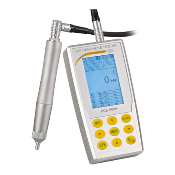
Manual System description Main structure and basic principle Front and back view of the ultrasonic hardness tester 1. 4-pin socket 2. 8-pin socket 3. Power button 4. USB-interface 5. Operation panel 6. Display... -
Page 8: Control Elements
Manual Control elements Button Designation Function Material In measurement mode: open material menu In material menu: choose material Measurement unit In measurement mode: choose measurement unit In material menu: delete In hardness scale menu: change between ASTM / DIN In test result menu: open search function In deletion menu: delete Enter In measurement mode: start measurement... -
Page 9: Display
Manual Display 1. Settings 2. Probe type 3. Measurement information 4. Material information 5. Measurement results 6. Single measurements of the test series 7. Measurement result Settings The following settings are displayed: Auto-save (on/off) Sound (on/off) Time Battery condition Probe type The instrument gives information on the assembled probe and its’... -
Page 10: Measurement Probe
Manual Measurement probe 8-pin socket Vickers diamond Note: The standard probe is preset to 20 N. Other probes are available as optional accessory. - Page 11 Manual Ultrasonic indenter and recesses During measurements the inspection stamp entrudes minimally within the material. The indentation depth (H) and the mean value of the dialog lengths (d) of the various probes of the ultrasonic hardness tester can be reduced with increasing value. Material hardness (HV) Depth (µm) Material hardness (HV)
- Page 12 Manual Material hardness (HV) Minimum material thickness (µm) Note: The table only shows the values for the 20 N probe. Condition of the surface The applied test force (i.e. the selected UCI probe) must not only match the application but also the surface quality and roughness of the material.
-
Page 13: Battery
Manual Battery The main unit includes a rechargeable battery (charger, 4.2 V, 4800 mAh). You can find the battery lid on the back of the device. When the battery is flat the symbol “ “appears in the upper right corner from the main menu, to remind you to charge the battery in time. -
Page 14: Operation
Manual Operation Initial operation Connect the angle plug of the 8-pin data cable to the 8-pin connector of the probe together. If you hear a clicking noise, the device is in the correct position. Now connect the other end of the 8-pin data cable to the 8-pin connector of the ultrasonic hardness tester. - Page 15 Manual 4. Hold the probe for about 2 seconds in this position until the measurement is complete. The device then sends a signal, which states that the measurement is complete and the measured values can be read from the display. The first reading is not included in the determination of the average value.
-
Page 16: Settings
Manual Settings Press the menu-button to get to the main menu. There are the following options: Test setup System setup Save setup Print setup Choose the required submenu and confirm with “Enter”. Test setup Calibration Here you can see all calibrations for the different materials that you have made. Choose the calibration you need by using the arrow buttons and confirm with the “MAT”... -
Page 17: System Setup
Manual System setup 8.2.1 Language option Here you can choose the language of the instrument. You may choose between English, Chinese, Portuguese, Turkish and German. Use the arrow keys to choose and the “ENTER” key to confirm. 8.2.2 Sound Here you can choose what sounds the instruments is supposed to make. Make your choice with the arrow keys and confirm with “ENTER”. -
Page 18: Print Setup
Manual Print setup Here you can print out all measured data or certain data slot. This works just as deletion or part-deletion works. Calibration Reasons to calibrate If the readings are stable in the process of reviewing the durometer with the reference block, but the nominal value of the reference hardness block is different. -
Page 19: Calibration With One Calibration Standard
Manual 9.3.2 Calibration with one calibration standard The calibration with only one calibration standard is similar to the calibration with two standards. The difference is that you do not calibrate the “TEST-H” part. Press the “MENU” key after “TEST-L” calibration and enter the nominal value. -
Page 20: 10 Disposal
Manual 10 Disposal For the disposal of batteries, the 2006/66/EC directive of the European Parliament applies. Due to the contained pollutants, batteries must not be disposed of as household waste. They must be given to collection points designed for that purpose. In order to comply with the EU directive 2012/19/EU we take our devices back.
Need help?
Do you have a question about the PCE-5000 and is the answer not in the manual?
Questions and answers