Table of Contents
Advertisement
Quick Links
Advertisement
Table of Contents

Related Manuals for PCE Health and Fitness PCE-COM 20


Summary of Contents for PCE Health and Fitness PCE-COM 20
- Page 1 User Manual PCE-COM 20 Conductivity Tester User manuals in various languages (Deutsch, français, italiano, español, português, nederlands, türk, polski, русский, 中文) can be downloaded here: www.pce-instruments.com Last change: 12 October 2017 v1.0 © PCE Instruments...
-
Page 2: Table Of Contents
Contents Safety notes ................... 1 Specifications ..................2 Technical specifications ....................2 Delivery content ....................... 3 Accessories ........................4 System description ................5 Device ..........................5 Connections and sensors ....................6 Function keys ........................6 Getting started ..................7 Power supply ........................7 Operation .................... -
Page 3: Safety Notes
Safety notes Please read this manual carefully and completely before you use the device for the first time. The device may only be used by qualified personnel and repaired by PCE Instruments personnel. Damage or injuries caused by non-observance of the manual are excluded from our liability and not covered by our warranty. -
Page 4: Specifications
Specifications Technical specifications Measuring frequency 60 KHz, sine wave 0.5 … 112 % IACS Conductivity 0.3 … 65 MS/m measurement range Resistance: 0.015388 … 3.33333 Ω*mm²/m 0.01 % IACS (at <51 % IACS) Resolution 0.1 % IACS (at 51 % IACS ... 112 % IACS) ±0.5 % at +20 °C Accuracy ±1 % at 0 ... -
Page 5: Delivery Content
Delivery content 1 x conductivity meter PCE-COM 20 1 x probe 1 x data cable 1 x user manual 1 x mains adaptor 3 x conductivity standard 1 x Allen key 1 x factory calibration certificate 1 x software 1 x carrying case... -
Page 6: Accessories
Accessories As an addition to the included standard conductivity blocks, further blocks can be purchased. The following list shows the available materials and the approximate conductivity values. Material Conductivity Conductivity % MS/m IACS Titanium 0.60 1.03 Bronze 4.70 8.11 Bronze 6.91 11.93 Bronze... -
Page 7: System Description
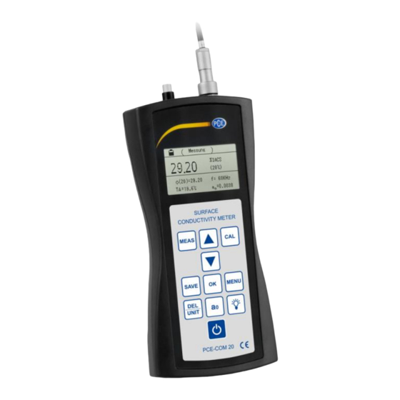
System description Device 01 Calibration key 05 Save key 09 Menu key 02 Arrow key “Up“ 06 Delete/unit key 10 Backlight key 03 Measuring key 07 Probe 11 a 04 Arrow key “Down“ 08 Confirmation key 12 On / off key ©... -
Page 8: Connections And Sensors
Connections and sensors 01 Probe connection 02 Temperature sensor 03 Connection for Mini USB cable 04 Connection for mains cable Function keys Function “MEAS“ Measurement “SAVE“ Storage of measurement data “CAL“ Calibration “MENU“ Function set-up / settings “OK“ Confirmation DEL: Deletion (in viewing mode) “DEL/UNIT“... -
Page 9: Getting Started
Getting started Power supply The device is powered by the included AC mains adaptor (input: 100 … 240 V AC; 50/60 Hz; output: 4.2 V DC / 1 A). The mains adaptor is connected at the bottom of the device. During operation, the integrated 2200 mAh lithium battery can be used. -
Page 10: Measurement
Measurement By pressing the „MEAS“ key, you can directly enter measurement mode from the welcome screen, from the calibration menu or from the settings screen (Image 2). Image 2 Notes In the upper area of the display (cf. „MEASUREMENT“) Image 2), you can see in what mode you currently are. -
Page 11: Notes On The Measurement
In order to make a measurement, the probe must be placed vertically and directly on the sample material for two seconds. The meter will then emit a sound to signalise that the conductivity measurement is completed. The measured data are automatically shown in the display and do not disappear before a new measurement is made. -
Page 12: Settings
Settings 1. Menu navigation The shortcut “SET“ is available in every mode and directs you to the settings as shown in the images 3-5. Image 3 Image 4 Image 5 © PCE Instruments... - Page 13 Ten different settings are available. Use the arrow keys to navigate through the settings and to highlight the desired option. You can confirm your selection by pressing the “OK“ key. If you want to return from one of the options to the overview of the different setting options, press the “SET“...
- Page 14 The current temperature “TA“ shows the ambient temperature during the measurement (measured by the temperature sensor). When you have selected “TC“ (underlined), press „OK“ to move the cursor to the displayed number. You can now change the number by means of the arrow keys to enter the material temperature.
- Page 15 5. Calibration block Image 9 The numerical values behind σ and σ can be set as conductivity values of the high-value calibration block and of the low-value calibration block at a temperature of 20 °C and are used for calibration. To select a unit, read chapter 5.4.7. The values of a and a can be set as temperature coefficients of the respective block.
- Page 16 6. Data storage mode Image 10 For information on how to use this function, read chapter 5.4.11. Use the arrow keys to select one of the two options and confirm with “OK”. You will then automatically get back to the previous screen. When you have switched the device off and back on, you will automatically be in manual storage mode.
- Page 17 8. Memory Image 12 In this option, you can see the saved data. Up to 500 data records can be saved. In the upper part of the display, next to “QUERY“, you can find the date of storage of the data record.
- Page 18 9. Data uploading Image 13 Image 14 Image 15 This function is used to transfer measurement data to your connected computer. The transfer starts with the most current position and ends with the last one. When you are in the settings overview and click on “DATA UPLOADING“, “READY“ (see image 13) will appear in the display.
- Page 19 10. Language selection Press one of the arrow keys to move the cursor within the overview and to select one of the positions. Press “OK“ to confirm your language selection and get back to the settings screen. You can select “German”, “English“ or “Chinese“. 11.
-
Page 20: Software Manual
- minimum resolution of 800x600, 4 GB RAM recommended - optional: printer - digital conductivity meter "PCE-COM 20" Installation Please execute "Setup PCE-COM 20.exe" and follow the instructions of the setup. Description of the interface Fig. 1 The main window (Fig. 1) contains the following sections: Below the title bar, there is a toolbar the icons of which can be selected and clicked on with your mouse. - Page 21 Meaning of the individual icons of the toolbar Group "connection" Connect with the "PCE-COM 20" Disconnect from the "PCE-COM 20" Group "data" Import measurement data from the "PCE-COM 20" Export measurement data Load a series of measurements from a file Save a series of measurements in a file Group "settings"...
- Page 22 If you wish to use a different language than the one selected during installation, you can select it via the corresponding icon in the toolbar (“Selection of a language supported by the system“). To enable the "PCE-COM 20" to work with the software, the assigned COM port must be set once.
- Page 23 Connect with the "PCE-COM 20" After making the desired settings and closing the settings dialogue by clicking on the "Apply" button, you can establish a connection to the "PCE-COM 20" by clicking on the corresponding icon ("Connect with the "PCE-COM 20"").
- Page 24 When the connection has been established successfully, all measurement values saved to the "PCE-COM 20" can be imported to the software as a cohesive series of measurements. After clicking on the corresponding icon on the toolbar ("Load a series of measurements from a file"), a new dialogue will appear (Fig.
- Page 25 After the import After completion of the data import, all values measured by the "PCE-COM 20" will be available in the software. Numerical display Fig. 5: Numerical display In the upper right-hand part of the main window (Fig. 5), all measurement values are shown in a chart.
- Page 26 Statistical data Fig. 6: Statistical data Below the chart, there is an area (Fig. 6) showing statistical data: Number of measured values belonging to a series of measurements, minimum and maximum values, span (maximum - minimum), median, arithmetic average, standard deviation, standard error and modal value.
- Page 27 Fig. 8: Renaming series of measurements If you would like to remove series of measurements from the software, you can highlight one or more identifiers in the list of series of measurements and delete them by pressing the "Del" key on your keyboard.
-
Page 28: Calibration
Note: After at least one completed import, the series of measurements will be kept within the memory of the computer until it is deleted or the software is closed. In the latter case, the software will show a hint that the current series of measurements has not been saved yet, which means that its complete content will be lost if you close the software (Fig. - Page 29 1. Calibration of the high value a When you are in the calibration menu, a calibration of the block with the high value will be required first. The set value of this block is marked with a , in the upper part of the display. On the lower, left-hand side of the display, the corresponding temperature coefficient will be shown.
-
Page 30: Maintenance
Maintenance Storage The device with all accessories should be stored in the carrying case included and at normal ambient temperature. The environment should be dry and constant. Avoid shocks and drops. Warranty You can read our warranty terms in our General Business Terms which you can find here: https://www.pce-instruments.com/english/terms. - Page 31 © PCE Instruments...
- Page 32 PCE Instruments contact information Germany France Spain PCE Deutschland GmbH PCE Instruments France EURL PCE Ibérica S.L. Im Langel 4 23, rue de Strasbourg Calle Mayor, 53 D-59872 Meschede 67250 SOULTZ-SOUS-FORETS 02500 Tobarra (Albacete) Deutschland France España Tel.: +49 (0) 2903 976 99 0 Téléphone: +33 (0) 972 3537 17 Tel.
Need help?
Do you have a question about the PCE-COM 20 and is the answer not in the manual?
Questions and answers