Table of Contents
Advertisement
Quick Links
Advertisement
Table of Contents

Related Manuals for PCE Health and Fitness PCE-PST1


Summary of Contents for PCE Health and Fitness PCE-PST1
- Page 1 Manual Test Device for Peel Tests PCE-PST 1 Version 1.0 Date of creation: 24.06.2015 Date of last change: 25.05.2016 Address:East Room 306,3th Floor,1st Building,Shenhua Industrial Park,Meihua Road, Futian District,Shenzhen City Tel:0755-32978297 Email:hj@pce-instruments.cn...
-
Page 2: Table Of Contents
Contents Introduction...........................4 Safety notes.......................... 4 Specification......................... 5 Technical specifications.......................... 5 Delivery contents............................5 System description......................6 Composition and components....................... 6 Display............................... 6 Controls..............................7 4.3.1 Force gauge..............................7 4.3.2 Test stand..............................8 Connectors..............................9 4.4.1 Force gauge..............................9 4.4.2 Test stand..............................10 Memory..............................10 Operation..........................11 Getting started............................11 Performing a test............................12 Settings.......................... - Page 3 Manual 6.3.12 Firmware update............................19 6.3.13 Defaults............................... 19 Software..........................19 Address:East Room 306,3th Floor,1st Building,Shenhua Industrial Park,Meihua Road, Futian District,Shenzhen City Tel:0755-32978297 Email:hj@pce-instruments.cn...
-
Page 4: Introduction
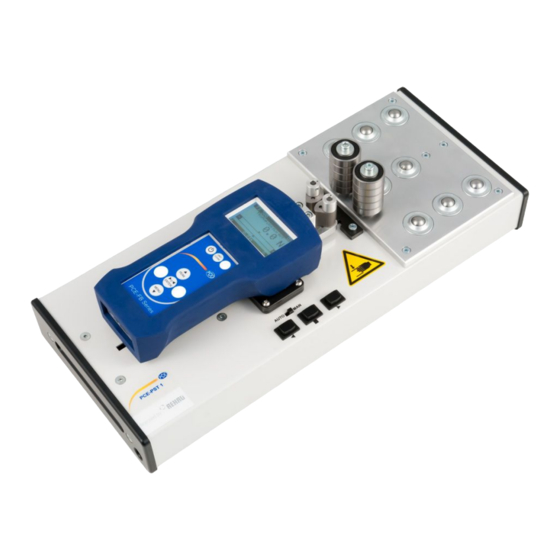
Manual Introduction Thank you for purchasing a PCE-PST 1 test device for peel tests from PCE Instruments. The PCE-PST 1 was designed for performing peel tests in a 90 ° angle and for measuring forces up to 500 N. To do so, the PCE-PST 1 comes with a PCE-FB 500 force gauge which is mounted on a motor-powered slide unit. -
Page 5: Specification
Manual Specification Technical specifications Test stand Measuring path 100 mm Travelling distance 150 mm Speed 0.3 m/min Force gauge Measuring range 500 N Resolution 0.1 N Accuracy ±0.1 % of measuring range Local gravity factor manually adjustable or via GPS data Trigger force for staring the measurement 20 N Measuring units... -
Page 6: System Description
Manual System description Composition and components Guiding pulleys Force gauge Control panel Claw Base plate with mechanism pulleys Display The display is located on the force gauge. The most important elements are described on the following image. Model Battery status indication Measuring mode Reading... -
Page 7: Controls
Manual Controls 3.3.1 Force gauge Name Function ON/OFF Turn the device on/off UNIT/CLEAR Main screen: Change the measuring unit Menu: cancel/back BACKLIGHT Turn the backlight on/off PEAK ▲ Main screen: Show peak values Menu: Move cursor up ... -
Page 8: Test Stand
Manual 3.3.2 Test stand Description Function Selector switch automatic/manual Choose between manual and automatic control of the slide unit’s movement (to the left) Start button Automatic: Start the automatic movement of the slide unit to the left. The slide unit moves across the whole travelling distance. -
Page 9: Connectors
Manual Connectors 3.4.1 Force gauge The connectors of the force gauge are located at the bottom side of the device (during normal use of the PCE-PST 1, this is on the left side). On the bottom of the forge gauge you can find an USB and a RS-232C interface, as well as a connector for power supply. -
Page 10: Test Stand
Manual 3.4.2 Test stand The connector for the power supply is located on the left side of the device (when standing in front of the control panel). Connector for mains adaptor (12 V / 5.0 A) Memory The recorded data is stored automatically to the volatile memory (RAM) of the force gauge. When you turn off the device, the data are lost. -
Page 11: Operation
Manual Operation Getting started To get started, follow these steps: 1. Charge the force gauge by using its mains adaptor (12 V / 1.2 A). Connect the mains adaptor of the test stand (12 V / 5.0 A) to the test stand. Note: It is recommended to operate the force gauge without the mains adaptor, when performing a measurement. -
Page 12: Performing A Test
Manual Performing a test To perform a peel test, follow these steps: 1. Follow the steps in chapter 5.1. 2. Make sure that the slide unit is in its starting position and that the claw mechanism is opened. 3. Prepare the sample by peeling off an approx. 6 cm long stripe. Preferably bend the stripe in a 90 °C angle. 4. - Page 13 Manual The measurement cannot be started. The sample is too long. When the sample is inserted correctly, you can start the measurement procedure. 5. Press the MEM button on the force gauge. A “TRG” indication should now appear in the display. Note: the following settings are set by default for peel tests: Mode: automatic...
-
Page 14: Settings
Manual 8. Now, you can read the measuring results in the display of the force gauge. 9. To move the slide unit back into its starting position, press and hold the back button on the test stand. Note: During this procedure, the claw mechanism opens. Hold the sample to prevent it from falling out. To start another measurement, you first have to delete the readings from the volatile memory. -
Page 15: Speed
Manual Measurement Select “Measurement” to open the measurement settings. Here you can choose between the following settings: 1. Speed 2. Unit 3. Auto-zeroing 4. Threshold 5. Direction 6. Peak 7. Exit 5.1.1 Speed Here you can change the sampling rate. You can choose between the following settings: ... -
Page 16: Threshold
Manual 5.1.4 Threshold Here you can set threshold values and turn on/off the threshold function. You can change the following options: 1. Status: ON/OFF – Activate/deactivate the threshold function. 2. MIN: Set the minimum threshold value. Enter a force. 3. MAX: Set the maximum threshold level. Enter a force. 4. -
Page 17: Configuration
Manual 5.2.2 Settings Here you can adjust the settings of the memory function. You have the following options: 1. Mode: MANUAL/AUTO – Automatic or manual measuring mode. 2. Quantity: Enter the quantity of readings to be saved in automatic measuring mode (max. 6,400). 3. - Page 18 Manual 5.3.2 Calibration If you have any questions, please contact our personnel. 5.3.3 Info Here you can view information about the measuring device, such as type, measuring range, serial number or production date. 5.3.4 Time & date Here you can adjust the date and time settings. You have the following options: 1.
-
Page 19: Battery
Manual 5.3.9 Auto Power Off Here you can configure the Automatic Power Off function. You have the following options: 1. Status: ON/OFF/BAT – Turn the function on/off or set it to Automatic Power Off after 5 min (BAT). 2. Exit 5.3.10 Battery Here you have the following options: 1. - Page 20 Manual 4. Now you get to the main screen of the software: Name Function Live graph Here you can see the readings from the force gauge in real-time as a graph. Current value Here you can see the current reading. Remote control Here you can control some functions of the force gauge remotely.
- Page 21 Address:East Room 306,3th Floor,1st Building,Shenhua Industrial Park,Meihua Road, Futian District,Shenzhen City Tel:0755-32978297 Email:hj@pce-instruments.cn...
Need help?
Do you have a question about the PCE-PST1 and is the answer not in the manual?
Questions and answers