
Related Manuals for PEERLESS DST940


Summary of Contents for PEERLESS DST940
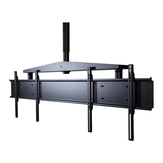
- Page 1 Installation and Assembly: Dual Display Ceiling Mount System Models: DST940 Extension pipe (sold separately) Max Load Capacity: 150 lb (68 kg) ISSUED: 08-10-09 SHEET #: 139-9011-4 01-07-2015...
-
Page 2: Table Of Contents
NOTE: Read entire instruction sheet before you start installation and assembly. WARNING • Do not begin to install your Peerless product until you have read and understood the instructions and warnings contained in this Installation Sheet. If you have any questions regarding any of the instructions or warnings, for US customers please call Peerless customer care at 1-800-865-2112, for all international customers, please contact your local distributor. -
Page 3: Parts List
Before you begin, make sure all parts shown are included with your product. Parts may appear slightly different than illustrated. Parts List Description Part # A 6" extension column 026-1014 B dual cross support 139-1015 C 4.5" hex bolt 520-9548 D 3/8-16 nylock nut 530-9310 E retaining collar... - Page 4 Security Adapter Bracket Fasteners M5 x 12 mm (8) M4 x 12 mm (12) M6 x 12 mm (8) M8 x 15 mm (12) 520-1064 510-1079 520-1050 520-1068 M6 x 20 mm (8) M5 x 25 mm (8) 520-9554 520-1122 M4 x 25 mm (8) M6 x 25 mm (8) M6 x 30 mm (8)
-
Page 5: Attaching Dual Cross Support To Extension Pipe
Attaching Dual Cross Support To Extension Pipe Slide dual cross support (B) onto end of extension WARNING pipe (sold separately) followed by extension pipe fi ber washer (F) and retaining collar (E). Tighten retaining collar so that thread is securely engaged. •... -
Page 6: Attaching Solid•Point
™ Attaching Solid•Point Column Mounts to Extension Columns Insert four M10 x 15 mm penta-pin screws (L) into threaded holes on the sides of ceiling arm box (H) as shown in fi gure 3.1. Leave approximately 1/4" of exposed thread as shown in detail 1. Slide ceiling arm box (H) onto end of extension column (A) followed by extension column fi... -
Page 7: (Optional) Attaching Dsx750 To Ceiling Arm Boxes
Attaching DSX750 To Ceiling Arm Boxes (Optional) Attach two adapter box (supplied with DSX750) to ceiling arm box (H) using four M10 screws (supplied with DSX750) per box as shown below. NOTE: Use DSX750 instructions to complete installation of adapter box (supplied with DSX750). M10 SCREWS (SUPPLIED WITH DSX750) ADAPTER BOX... -
Page 8: Attaching Adapter Brackets To Screens
Installing Adapter Brackets WARNING • Tighten screws so adapter brackets are fi rmly attached. Do not tighten with excessive force. Overtightening can cause stress damage to screws, greatly reducing their holding power and possibly causing screw heads to become detached. Tighten to 40 in. • lb (4.5 N.M.) maximum torque. •... - Page 9 SCREEN MULTI-WASHER SCREW ADAPTER BRACKET (P) If you have any questions, please call Peerless customer care at 1-800-865-2112. For Bump-out or Recessed Back Screen Refer to Screen Compatibility Chart to determine the proper fastener to use. Visit www.peerlessmounts.com/2 for a full screen compatibility chart for this mount.
-
Page 10: Attaching Adapter Brackets To Adapter Plate
DETAIL 4 fi g. 7.1 fi g. 7.2 10 of 10 ISSUED: 08-10-09 SHEET #: 139-9011-4 01-07-2015 © 2010, Peerless Industries, Inc. All rights reserved. All other brand and product names are trademarks or registered trademarks of their respective owners.
Need help?
Do you have a question about the DST940 and is the answer not in the manual?
Questions and answers