
Related Manuals for PEERLESS Mobile Videowall Trolley PDVWM 2x2 46 55 L


Summary of Contents for PEERLESS Mobile Videowall Trolley PDVWM 2x2 46 55 L
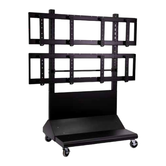
- Page 1 Installation and Assembly: 2 x 2 Cart Model: DS-VWC560 Maximum Load Capacity 500 Ibs (227 kg) 1 of 10 ISSUED: 03-08-11 SHEET #: 125-9195-5 09-20-12 Visit the Peerless Web Site at www.peerlessmounts.com For customer care call 1-800-865-2112.
-
Page 2: Parts List
PARTS LIST Description Qty. Part # A vertical support 145-1389 B adapter brackets 145-1711 C horizontal support 124-1852 D horizontal rail 145-1238 E 5" caster 600-0026 F 1/4" flat washer 540-9440 G M8 x 25 mm phillips screw 520-1031 H 5/16 flat washer 540-9406 I 5/16 split washer 540-9405... - Page 3 3 of 10 ISSUED: 03-08-11 SHEET #: 125-9195-5 09-20-12 Visit the Peerless Web Site at www.peerlessmounts.com For customer care call 1-800-865-2112.
- Page 4 Assembling Cart Attach two horizontal supports (C) to vertical support (A) using eight 1/4-20 x 3.5" hex head screws (J), 1/4" SAE washers (F) and 1/4-20 nylock nuts (K). Attach horizontal support (C) to vertical supports (A) Attach horizontal supports (C) to second using eight 1/4-20 x 3.5"...
- Page 5 Attach four swivel casters (E) to vertical supports (A) using sixteen M8 x 25 mm pan phillips screws (G), split washers (I) and 5/16" SAE flat washers (H). Determine position of horizontal rails (D) using the formula below. 1. locate the position of the lower horizontal rail (D) and attach to vertical supports (A). 2.
-
Page 6: Cable Management
Attach horizontal rails (D) onto vertical supports (A) using sixteen 1/4-20 x 3.5" hex head screws (J), 1/4" SAE washers (H) and 1/4-20 nylock nuts (K) as shown in detail 1. Make sure that horizontal rails (D) are level then tighten all 1/4-20 x 3.5"... - Page 7 Attach adapter brackets (B) to back of display using four M6 x 12 mm phillips screws (O) with nylon shoulder washer (L), or four M8 x 15 mm phillips screws (N) as shown below. Adapter Bracket Mounting Patterns 200 mm MIN 600 mm MAX 400 mm 200 mm...
- Page 8 Hook display and adapter brackets (B) onto horizontal rail (D) as shown below. NOTE: Hang displays in sequenced order. NOTE: Once display is located in desired position, tighten security screws as shown in detail 4. Attaching Component Shelf (Optional) Fasten component shelf (W) onto horizontal support (C) using three self-drilling phillips screws (CC) as shown below.
- Page 9 Adapter Bracket Adjustment Use legend below to determine position of display. NOTE: Each knob can be adjusted independently for fine tuning angle adjustments. Turn knobs CLOCKWISE to raise display height. Turn knobs CLOCKWISE to push out display. Turn knobs COUNTER-CLOCKWISE to lower display height. Turn knob COUNTER-CLOCKWISE to pull in display.
- Page 10 Attaching Covers NOTE: Position bottom front and back covers first position front bottom cover (U). Secure covers in place using four decorative screws (Y) as shown below. position back bottom cover (V). Secure covers in place using four decorative screws (Y) as shown below. position front top cover (AA).
Need help?
Do you have a question about the Mobile Videowall Trolley PDVWM 2x2 46 55 L and is the answer not in the manual?
Questions and answers