
Related Manuals for PoolCop Evolution

Summary of Contents for PoolCop Evolution
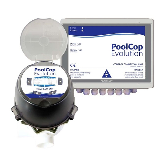
- Page 1 PoolCop Evolution ® Installer and User Manual Date: October 8, 2018 Manual Version: V42EN Firmware Version: V42 Product Versions: PoolCop Evolution...
- Page 2 P a g e | 2 P o o l C o p M a n u a l : V 4 2 E N www.poolcop.com PCFR...
-
Page 3: Table Of Contents
Maintenance ..................................88 Configuration Menu ................................90 Section 6 Internet connection ......................103 Introduction ..................................103 PoolCop Connection to the Web ........................... 104 Server Connection and Pool Setup ..........................105 PoolCopilot Functions ..............................108 Troubleshooting ................................108 Section 7 Technical Specifications ....................109 PoolCop Evolution ................................ - Page 4 Figure 22 – Binary combination ..............................................29 Figure 23 – Davey ProMaster VSD400 ............................................ 29 Figure 24 – PoolCop water analysis sensor .......................................... 30 Figure 25 - Sensor and Housing ............................................... 30 Figure 26 - Sensor Housing plug ............................................. 30 Figure 27 –...
-
Page 5: Introduction
P a g e | 5 NTRODUCTION Section 1 Notes, Cautions, Warnings and other Definitions ......................6 Declaration of Conformity CE ............................7 Important Information, Safety Notices and Precautions ....................7 Norms and connexions ............................... 7 Location and Handling ................................ 8 www.poolcop.com PCFR... -
Page 6: Notes, Cautions, Warnings And Other Definitions
The instructions or procedures depend on whether the equipment is installed. As required The instructions, procedures, or requirements are mandatory depending on relevant conditions. A planned change in an indication, annunciation, or message is observed to occur as expected. Check the Verify state or condition prior to proceeding. www.poolcop.com PCFR... -
Page 7: Declaration Of Conformity Ce
Instructions given below are all important for your safety. Your PoolCop is a product of superior design, engineering and manufacture and should be treated with care. The information contained in this section will help you fulfil the warranty obligations and enjoy this product for many years. -
Page 8: Location And Handling
P o o l C o p M a n u a l : V 4 2 E N Loca t ion a nd H a ndling Your PoolCop is reliable, easy to operate and of robust design. All electronic equipment, however, must be handled with care. Use PoolCop and the associated equipment only for the purpose intended. -
Page 9: Warranty, Records
PoolCop Warranty ................................11 PoolCop Configuration Card ............................12 Routine Maintenance ................................ 13 Routine Pool Maintenance ............................... 13 PoolCop Maintenance ............................... 13 Closing the pool for the winter (Winterise) ........................16 Re-commissioning the PoolCop for the Season ......................16 www.poolcop.com PCFR... -
Page 10: Poolcop Warranty Registration Card
84160 CUCURON result in your product not being registered. France www.poolcop.fr Email: contact@poolcop.fr Product: PoolCop 1.5” PoolCop 2” Brand / Model N°: Name of Installer: Serial Number: Installer’s Company: Purchased From: Telephone:... -
Page 11: Poolcop Warranty
• any direct or any indirect prejudice linked to the unavailability of the product for whatever duration • Postal address: PCFR SAS, La Remise, 130 Boulevard du Nord, 84160 CUCURON, France www.poolcop.com PCFR... -
Page 12: Poolcop Configuration Card
Function: Function: Action when: OPEN/CLOSE Alert Y / N Action when: OPEN/CLOSE Alert Y / N PoolCop: Optional Integrated Water Treatment pH Control (Aux 7) Remnant Injection Installed: YES / NO MAX Dosing: Installed: YES / NO Aux Channel: Aux……. -
Page 13: Routine Maintenance
Basic maintenance needs to be carried out to ensure that your PoolCop successfully manages your pool. Regular Periodic Checks Check for Alerts: Alerts and notifications are PoolCop’s way of communicating with you about the state of the pool. Check the Alerts regularly or at any time when in doubt about a condition. - Page 14 P o o l C o p M a n u a l : V 4 2 E N Visit check list The following check will help you to maintain PoolCop in good conditions and to optimize your visits. Date...
- Page 15 Inspect Valve Gasket, Grease. Annual Service Replace Valve Diffuser Replace Battery Calibrate Sensors Check Leaks, Grease. Annual Service Check Battery Calibrate Sensors Check Leaks Inspect Valve Gasket, Grease. PoolCop is guaranteed for 2 years provided that warranty conditions are met. www.poolcop.com PCFR...
-
Page 16: Closing The Pool For The Winter (Winterise)
Leaving Your Pool, Going on Holiday When leaving your pool for a few weeks, such as when going on holiday, your PoolCop will take care of all filtration and water treatment as normal. It is recommended that you do the following quick checks, prior to leaving on holiday: Remove all leaves and debris from the pool and baskets. -
Page 17: Installation Guide
Connecting an Automatic Valve on Waste Line ......................45 Connecting Inputs ................................46 Connecting equipment ..............................48 Completing the Installation .............................. 51 Commissioning PoolCop ..............................51 Post Installation Inspection, Documentation, Procedures ................... 52 Post Installation Inspection .............................. 52 Post Installation Documentation ............................. 52 Post Installation Procedures ............................. -
Page 18: General
This installation manual is intended to be used as a checklist; check the boxes next to installation steps to ensure that all steps are completed in the correct sequence. It is recommended that the PoolCop Configuration Card be used to keep notes of settings, configuration and notes during the installation; this will facilitate easy completion of the required post installation documentation. - Page 19 XM8 Extension Module with 8 inputs and 8 relays outputs. Before starting the PoolCop installation, the installer must confirm the following in direct discussion with the pool owner: Valve Data Unit is compatible with the pool’s filter.
-
Page 20: Installing The Valve Data Unit
CAUTION: Incorrect gluing negatively affects the bonding quality and water tightness. The valve housing is made with ABS, slip threaded pieces and PoolCop connector kits are in ABS. Never use solvents, solvent based cleaners or primers. Never use solvent based adhesives. -
Page 21: Figure 7 - 2.0" Valve O-Ring
TOP MOUNT On a standard top mount filter, check the alignment indicator on the valve housing and ensure that the waste pipe is at the three o’clock position with respect to the PoolCop Valve Data Unit. CAUTION Apply a layer of pure silicon grease provided) on the wagon wheel gasket and inside the valve housing. You can also apply some grease or lubricant to the O-ring gaskets. -
Page 22: Installing The Control Connection Unit
Live and neutral are on the edges. Protective earth is in the middle. Before powering up: Check the 115V/220V selector position; slide selector to the left for 220/240VAC power supply, slide to the right for 115/120VAC. Check that the internal switch on the electronic board in ON. www.poolcop.com PCFR... -
Page 23: Figure 11 - Terminals
Table 1 Relays and Power Ratings WARNING: Never exceed the power ratings. Always conform to local installation norms and requirements. CAUTION: If you are unsure of the applicable wattage rating, contact the distributor of the auxiliary apparatus to confirm prior to connection. www.poolcop.com PCFR... -
Page 24: Figure 12 - Single Phase Pump Connection
Figure 12 - Single Phase Pump Connection If connecting a three-phase pump: The pool pump will have an independent supply, and the PUMP relay K1 will be used to control the external three-phase pump relay. Figure 13 - Three-Phase Pump Connection www.poolcop.com PCFR... -
Page 25: Figure 14 - Pentair Intelliflo Vsd With Intellicomm
P a g e | 2 5 Con nect i ng a V a r ia ble Speed Pum p See the VARIABLE SPEED PUMPS GUIDE downloadable on our internet website www.poolcop.com in RESOURCES /DOWNLOADS section for compatibility, connection, control and programming. -
Page 26: Figure 16 - Hayward Ecostar
P o o l C o p M a n u a l : V 4 2 E N Hayward EcoStar Speed Pump Aux1 Aux2 Aux3 HAYWARD EcoStar STOP Figure 16 - Hayward EcoStar Hayward VSTD Series Speed Pump Aux1 Aux2 Aux3 HAYWARD VSTD STOP Figure 17 - Hayward VSTD Series www.poolcop.com PCFR... -
Page 27: Figure 18 - Speck Badu Eco-Touch
BADU Eco Touch-Pro STOP Pulse ON 1 OFF 2 OFF 3 OFF Figure 18 - Speck Badu Eco-Touch Speck BADU 90 Eco Motion Speed Pump Aux1 Aux2 Aux3 BADU 90 Eco Motion STOP Figure 19 - Speck Badu Eco Motion www.poolcop.com PCFR... -
Page 28: Figure 20 - Zodiac Flopro Vs
P o o l C o p M a n u a l : V 4 2 E N Zodiac FloPro VS Speed Pump Aux1 Aux2 Aux3 ZODIAC FloPro VS STOP Figure 20 - Zodiac FloPro VS Invertek Optidrive inverter e Speed Pump Aux1 Aux2 Aux3 INVERTEK OPTIDRIVE STOP Figure 21 - Invertek Optidrive e2 inverter www.poolcop.com PCFR... -
Page 29: Figure 22 - Binary Combination
This is option is not related to a specific pump, but can be used to control several mono speed pumps. Speed Pump Aux1 Aux2 Aux3 Binary Combination STOP Figure 22 – Binary combination Davey ProMaster VSD400 Speed Pump Aux1 Aux2 Aux3 DAVEY ProMaster VSD STOP (33%) (50%) (67%) 4(83%) (100%) BCKWSH Figure 23 – Davey ProMaster VSD400 www.poolcop.com PCFR... -
Page 30: Water Treatment
Water treatments can be controlled using timers (slaved to filtration/circulation) or using water condition sensors and internal algorithms. There are three types of sensors available, the sensors have the same dimensions and fit the same housing in the PoolCop Valve Data Unit:... - Page 31 Reconnect the pump circuit breaker. Reset the filtration timers and mode as required. Start the pump from MANUAL CONTROL menu and check for leaks. Leave the pump running or switch the pump from MANUAL CONTROL menu, as required. www.poolcop.com PCFR...
-
Page 32: Ph Control
The electrode can be calibrated using pH buffer fluids or liquids of known pH. It is recommended to calibrate pH using an external buffer liquid or pool water in an isolated container, rather than in the PoolCop itself. This avoids the risk of stray currents in the pool affecting the calibration sequence. -
Page 33: Figure 28 - Ph Dosing Pump Connexion
Figure 28 – pH Dosing pump connexion Test and prime the dosing pump: WATER AND TREATMENT, CONTROL, select priming ON. pH Control Programming Refer to 5.4.2 pH Control. Activating pH Control In the MAINTENANCE menu, command the PoolCop to MEASURE www.poolcop.com PCFR... -
Page 34: Figure 29 - Example Of Connecting Dosing Pump To Aux6
Always wear correct chemical resistant hand protection when handling chemicals. EYE PROTECTION: Always wear correct eye protection when handling chemicals. PoolCop is compatible with all types of water disinfection. Disinfection can be with or without chemicals. Means of disinfection 3.5.4.1.1... -
Page 35: Figure 30 - Example Of Solenoid Valve Connection For Flow Control Via Aux3
Chemical Dosing, by Flow Control Tablet chemicals (such as chlorine or bromine) can be dosed as disinfectant or remnant, controlled by PoolCop using timers on any available Auxiliary relays, by means of a flow control valve with 24VAC supply (typically). -
Page 36: Figure 31 - Salt Sytem Connection
Other External Disinfection Equipment PoolCop auxiliary relays may be used to control the electrical power supply to external water disinfection equipment such as UV, Ozone, etc. Relays can also be used to control injection of chemicals (chlorine, etc.) using Timed Daily Control. - Page 37 CAUTION: Ensure that this time programmed is during a filtration cycle so that the dosing is carried out at a time that the filtration system is running. www.poolcop.com PCFR...
-
Page 38: Installing Options
NSTALLING PTIONS Various PoolCop options are available. These serve to increase autonomy and enhance functionality. Air T em per a t ur e Sensor The optional Air Temperature sensor measures outside air temperature, displays this on the screen, and the temperature is used for antifreeze protection if this protection is configured in the Pool Data menu. -
Page 39: Figure 33 -Water Line Level Sensor
Figure 34 - Buffer tank water level sensors PCB Label Cable colour Tag on the sensor WL (COM) Blue WL (LOW) Blue WL (HIGH) Blue WL (PROT) Blue Table 3 Buffer tank Version, with 4 sensors www.poolcop.com PCFR... -
Page 40: Figure 35 - Connecting Water Level
Connect the 2 core wire from the valve solenoid to the connector on J13 marked SOL (24V AC) according to Figure 35 - Connecting Water level. Polarity is not important. Reconnect electrical power supply to the PoolCop CCU. Switch the CCU ON. -
Page 41: Figure 36 - Cables Entries
Extension Module connector Figure 36 - Cables entries Figure 37 – Terminals See the appropriate section of this manual for connection details. Feed auxiliary equipment supply cables through a compression gland into the Extension Module. Switch the CCU ON. www.poolcop.com PCFR... - Page 42 IN10-GND Consumables low, pump start, pump stop, pool cover(*), etc. Table 5 Inputs Table CAUTION: Inputs are self-powered with low voltage Only use potential free signal without any external power supply. (*) see extras functionalities in 5.6.6 Equipment www.poolcop.com PCFR...
-
Page 43: Figure 38 - Auxiliaries Connection Terminal In Ccu (Left) And In Xm8 Extension Module (Right)
The electrical supply for any of the auxiliaries can be: 110VAC mains power supply: it is recommended that the PoolCop AUX relay controls an external relay to supply power. 230VAC mains power supply: it is recommended that the PoolCop AUX relay controls an external relay to supply power. -
Page 44: Figure 39 - Single Phase 230Vac Auxiliary
P o o l C o p M a n u a l : V 4 2 E N Figure 39 - Single Phase 230VAC Auxiliary Figure 40 - Three-Phase 380VAC Auxiliary Connection Figure 41 - Connection 24VAC Auxiliary www.poolcop.com PCFR... -
Page 45: Figure 42 - Additonal Relays
The valve must be controlled via the AUX5 relay and must be appropriately programmed in the 'Filter data" section. Figure 43 - Waste valve connexion Usually pilot solenoid valves are controlled with 24VAC which is available inside PoolCop CCU. www.poolcop.com PCFR... -
Page 46: Figure 44 - Connecting Inputs In Ccu
P o o l C o p M a n u a l : V 4 2 E N Con nect i ng I nput s Several types of sensors can be connected to the PoolCop to add functionality and trigger alerts. Inputs must be connected between the chosen input channel and the GND. -
Page 47: Figure 46 - External Thermostat
Pool Cover Detection An external pool cover sensor can be connected to an input to inform PoolCop that the cover is in the closed position. Programming in the Pool Data menu then allows for adjustment of filtration duration (in ECO+) and water treatments. -
Page 48: Figure 50 - Pool Cover Connexion (Control And Position)
Figure 50 - Pool Cover connexion (control and position) NOTE: Refer to the Pool Cover manufacturer wiring diagrams to wire properly the signals. Aux14 is open command, Aux 15 is close command and In10 is closed position contact. Figure 51 - Connection example with MecaTecCenter cover www.poolcop.com PCFR... -
Page 49: Figure 52 - Connection Example With Astral Roussillon Cover
Note * (1): If 8 and 9 are not interconnected, the cover can only be operated with the key on the local control panel. Otherwise, the key will no longer has any effect, and the control of the cover is always possible either locally either remotely. Note * (2): In the configuration menu, assign function F1 (Open) for relay R2. www.poolcop.com PCFR... -
Page 50: Figure 54 - Jetstream Connection
Figure 54 - Jetstream connection NOTE: Push button signal must be converted in ON/OFF contact before being connect to PoolCop Extension Module. This is usually done by a pneumatic switch inside the Jetstream electric box. Aux13 is Jetstream pump command. -
Page 51: Completing The Installation
If this equipment stays on for longer than 2 seconds, IMMEDIATELY switch OFF the CCU. Recheck all connections. If only the pump runs, disconnect the circuit breaker, switch ON the PoolCop and reset factory default settings. Now reconnect the pump circuit breaker and continue with commissioning. -
Page 52: Post Installation Inspection, Documentation, Procedures
Encourage the client to return the product warranty registration card. Post I nsta lla tio n Pr ocedur es Ensure that the client has a broad knowledge of the installation, understands the functions of the PoolCop and the implications of the various alerts: Introduce system and point out main components and their functions. -
Page 53: User Guide
Configuration ..................................60 Using and Settings ................................61 Illuminate the Backlight ..............................61 Navigate the PoolCop Menu ............................61 Return to Main PoolCop Display ............................. 61 Filtration and Pump Control............................. 62 Water Level Control ................................70 Water Treatment ................................71 Auxilairy Control ................................ -
Page 54: 4.1 Your Poolcop Configuration
Your pool will be a healthier swimming environment for you to enjoy with your friends and family. Remember, your PoolCop is not a repair system. Pay prompt attention to any Alerts given by the PoolCop. In the unlikely event of malfunctions do not hesitate to call your installer. -
Page 55: Menus
Filtration Modes Equipment Water Level Auxiliaries pH Control Water and Treatment ORP Control Remnant Injection Temp. adjustment Air Antifreeze Service Mode Maintenance Stop Treatment Measure pH Calibrate pH Pool Data Pump Data Filter Data Configuration Inputs Factory Settings Equipment www.poolcop.com PCFR... -
Page 56: Manual Control
BYPASS position at any time. Stops the pump (if ON) and manually rotates the valve to Rinse RINSE position at any time. CLEAN INHIBITED NOT AVAILABLE WITH AUTO Command Equipment Equipement Manually command equipment such as pool cover or Jetstream pump www.poolcop.com PCFR... -
Page 57: Filtration Modes
Program filtration timers and duration, manually or in automatic modes. Whenever quitting the FILTRATION MODES menu, PoolCop checks and adjust the status of the pump and auxiliaries, and switches them ON or OFF as required to match programmed running times. Cycle1 =00:00-00:00 Filtration is stopped. -
Page 58: Auxiliaries
Whenever quitting the AUXILIARIES menu, PoolCop checks and adjust the status of the pump and auxiliaries, and switches them ON or OFF as required to match programmed running times. AUX channels operate in the same manner, but some channels may be required for specific functions. -
Page 59: Water And Treament
Set parameters for pH Control. Max Dosing Priming Installed Disinfectant type Setpoint ORP Control Set parameters for ORP Control. BOOST day BOOST to Priming Installed Aux Channel Injection rate Temp adjust Remnant Injection Set parameters for remnant injection Extra adjust priming www.poolcop.com PCFR... -
Page 60: Maintenance
Set function and action and alarm for each input. Alert Network View Network settings Date/Time Set date and time. Factory Settings Language Select the language. Reset Reset to the default settings. PoolCover Set the Pool Cover control Equipment JestStream Set the Jetstream control Attractions Reserved www.poolcop.com PCFR... -
Page 61: Using And Settings
Every display has a 15 second timeout to go back to Maintenance the previous menu. The display will timeout to the Configuration main POOLCOP display within approximately 1 minute. S E L E C T Q U I T www.poolcop.com... -
Page 62: Filtration And Pump Control
Start the Pump Normally, the filtration pump is controlled automatically by PoolCop using filtration in manual timer or automatic modes. If, however you want to run the pump at another time, or need to restart the pump after stopping it for any reason, this is done from MANUAL CONTROL. - Page 63 Change the Pump Speed This feature is available with variable speed pumps only; for installation configuration see the PoolCop Variable Speed Pump Guide. Pump speed is linked to filtration and filter cleaning cycles; the speed can be changed by the user with the pump ON and this speed will be maintained until the next programmed Filtration Timer cycle commences or until the next filter cleaning cycle starts.
- Page 64 Your PoolCop now automatically controls the pump and filter system to carry out a backwash and a rinse cycle based on settings programmed. The display will show progress and pressures as your PoolCop cleans the filter automatically. Once the cycle is complete, the system returns to normal operation.
- Page 65 0 1 / 0 6 / 2 0 1 4 Valve : Filter Pump AUTO : 0.98 On the PoolCop main display, next to Pump you will see the Water Temp : 28 °C mode in which the pump and filtration are running, or OFF.
- Page 66 TIMER mode, filtration durations are not managed by PoolCop but chosen by the end user who must then make sure to correctly set the duration according to pool needs. A too long duration will waste energy and a too short one may not allow to keep the pool in good conditions.
- Page 67 Filter; activating the mode will reposition the valve to Filter. FORCED mode, the maximum daily duration is limited to 23:00; with either one or two stopped periods to allow for PoolCop measurement functions and daily self-test to occur. Normal automatic filter cleaning may occur during FORCED mode.
- Page 68 It is recommended to set both filtration cycles (Cycle 1 and Cycle 2) for best results. It is recommended to leave a gap of at least 30 minutes between two timer cycles to allow PoolCop to take necessary measurements make subsequent adjustments and carry out the periodic backwash if selected.
- Page 69 PoolCop has two means of detecting a freezing risk. It is recommended that BOTH freezing protections be utilized and that freezing protection be selected ON in the POOL DATA menu throughout the year.
-
Page 70: Water Level Control
Bypass Scroll UP or DOWN to place cursor at WASTE. Rinse Press SELECT; the pump will stop (if ON) and the S E L E C T Q U I T valve will rotate to the WASTE position. www.poolcop.com PCFR... -
Page 71: Water Treatment
Setting any timer to 00:00-00:00 (or any combination with same start and stop times) deactivates that timer. Whenever quitting the AUXILIARIES menu, PoolCop checks and adjust the status of the auxiliaries, and switches them ON or OFF as required to match programmed running times. Switch Auxiliaries ON/OFF... -
Page 72: Equipment Control (Requires Xm8 Extension Module)
> Command Open: executed. Command Close: Press SELECT to launch the command. Position: close When both commands are OFF, the motor is stopped. Actual cover position is shown. S E L E C T Q U I T www.poolcop.com PCFR... -
Page 73: Service Mode
S E L E C T Q U I T Ser vice m ode In service mode, PoolCop stops all its automatic actions. Service mode can be activated directly from the main screen by 1 2 : 4 6 : 0 1... -
Page 74: Troubleshooting And Alerts
Temperature Indicating Unusually High Temperature indicating high is caused by a short circuit in the temperature sensor. This could be caused by corrosion or by humidity in the PoolCop Valve Data Unit. Check for water in the Valve Data Unit. -
Page 75: Electrical Power Failure
P a g e | 7 5 Elect r ica l Pow er F a ilur e Your PoolCop will automatically detect a mains power supply failure and revert to the safe and low power mode, powered by the backup battery. -
Page 76: Alerts And System Messages
Aler t s a nd Sy st em M essa g es An Alert or a System Message is the way PoolCop notifies you of something out of the ordinary. The ALERT button flashes to attract your attention. Alerts can be one of four types: REMIND: a task that should be done soon to prevent any deterioration of pool condition. -
Page 77: Programming Guide
Stop water treatment ................................ 88 Measure pH ..................................88 Calibrate pH ..................................89 Configuration Menu ................................90 Pool Data ..................................... 90 Pump Data ..................................92 Filter Data .................................... 94 Inputs ....................................96 Factory Settings.................................. 98 Equipment ..................................100 www.poolcop.com PCFR... -
Page 78: Prior To Commencing Programming
On completion, verify that the valve position is Filter, and start the pump in Manual Operations. This allows the PoolCop to stabilize pressures and to measure water temperature and other data. The filtration system must run (in Filter or Bypass) for at least 10 minutes on first start or after reset to record stable water temperature for automatic filtration duration calculations. -
Page 79: Filtration Mode Menu
Set Cycle 1 as desired. Duration will be taken into account when FORCE72H calculating Cycle 2 duration. Set the Cycle 2 Filtration ON time. PoolCop calculates and sets the OFF time, with X indicated. The duration is automatically calculated based on the average measured temperatures during filtration in the last 24 hour period. -
Page 80: Cycle 1 Times
The first time ECO+ mode is selected, the duration of Cycle 2 will default to 8 hours. Once the filtration has run for approximately 10 minutes an accurate measurement of pool water temperature will enable your PoolCop to update the filtration duration. Cy cle 1 T im es... -
Page 81: Auxiliaries Menu
Q U I T Whenever quitting the AUXILIARIES menu, PoolCop checks the status of the auxiliaries, and switches them ON or OFF as required to match programmed running times. Auxi lia r y I D The default auxiliary ID is the Aux number. Each auxiliary can be renamed for ease of Text: use and identification. -
Page 82: Aux" Times (Timer Mode)
Auxiliaries can be set to run only on selected days of the week. Text: Weekday This is ideal for equipment such as pool cleaners and irrigation, which can be run on Default: ON (ALL) specific days of the week. Entries: Tue; Wed; Thu; Fri; Sat; www.poolcop.com PCFR... -
Page 83: Water And Treatment Menu
Q U I T When PoolCop is updating the water level, the last known value blinks on the screen. No action will be taken as long as the new level is not refreshed (displayed level value will stop blinking). An update is performed every 15minutes when the pump is stopped. - Page 84 Draining Set the duration for the water reduction cycle; Default: 120 seconds If the level is detected V_HIGH, then PoolCop will reduce water level following this Entries: 10–600 seconds logic: Water will preferably be consumed for backwashing the filter (if permitted, see 5.6.3 Filter Data), otherwise it will be sent to waste.
-
Page 85: Ph Control
Setpoint current temperature °C Text: SetPoint xx °C PoolCop automatically adjusts the required pH Setpoint as a function of temperature Display of Data only to ensure year-round optimal water treatment. This adjusted Setpoint is displayed against current water temperature. This corrected Setpoint is the actual value of pH the PoolCop will aim to maintain. -
Page 86: Orp Control
S E L E C T Q U I T 5.4.3.1.1 Installed INSTALLED: YES, PoolCop will control the ORP according to set point value. Text: Installed ORP Control display will be activated; ORP Control Alerts will be activated. Default: If set to NO, these functions are deactivated. -
Page 87: Remnant Injection
S E L E C T Q U I T volume actually injected may not fit the requirements. 5.4.4.1.1 Installed INSTALLED: YES, PoolCop will control the Remnant injection according to Text: Installed parameters settings Default: If set to NO, this function is deactivated. Entries: YES;... -
Page 88: Maintenance
S E L E C T Q U I T Ad just w a ter temper a t ur e Allows you to align PoolCop temperature indication to third party equipment like a Text: Temp heat pump by adding an offset to the temperature indication. -
Page 89: Calibrate Ph
/DOWLOADS section. NOTE: During the calibration process, PoolCop compares the "offset" of the probe to the signal that would be delivered by a perfect probe. This offset is essentially related to wearing. If the offset is too large, calibration is not possible. -
Page 90: Configuration Menu
C O N F I G U R A T I O N Pool Data Pump Data Filter Data Inputs PoolCop configuration menu Factory settings Equipment S E L E C T Q U I T Pool D a ta... - Page 91 Filtration Reduction when pool cover is detected closed To be effective, this functionality assumes the connection of pool cover, or mobile floor limit switch to a PoolCop input. (see 5.6.4 Inputs). Depending if pool is configured with a single or multi-speed pump, reduction strategy is different: 5.6.1.5.1...
-
Page 92: Pump Data
UP arrow and press SELECT; now use the arrows to select the pump make and Entries: SINGLE SPEED PUMP; model installed. Refer to the PoolCop Variable Speed Pump Guide for further PENTAIR IntelliComm ; details including connecting and programming. PENTAIR SuperFlo VS ;... - Page 93 If the alert “WARN: VALVE ROTATION valve rotation inhibited dur high static pressure” displays when the valve should rotate, increase this setting incrementally and progressively. Activate Pump Protection PoolCop protects the pump, by switching OFF the pump and integrated water Text: Prot. Pump treatments in the event pressure measured is below the Prot.
-
Page 94: Filter Data
Waste Valve Select YES if an automatic waste valve is fitted on the waste line. This valve, Text: Waste Valve controlled by Aux5, will be opened by PoolCop when the "main" valve is on Waste, Default: Backwash or Rinse positions. Entries: YES;... - Page 95 Refer to the filter manual for recommended backwash duration. Entries: – seconds, second increments Rinse Displayed if CLEANING: AUTO CLEANING: MANUAL. Text: Rinse Set the desired rinse duration. Default: 20 seconds Refer to the filter manual for recommended rinse duration. Entries: 10 – 180 seconds www.poolcop.com PCFR...
-
Page 96: Inputs
Alert : NO Set digital inputs identifier and behaviour S E L E C T Q U I T Input Name Various inputs can be installed and configured for use with PoolCop. Text: None Default Available Entries: Available; Thermostat AntiFrz;... - Page 97 Generates an alarm in the non-closed position. If the pool is equipped with a variable speed pump, PoolCop switches on the speed n ° 1. When the cover is re-opened during a cycle of operation of the pump, the speed associated with this cycle is restored.
-
Page 98: Factory Settings
S E L E C T Q U I T MC: is the MAC address, you will need this information to declare your PoolCop on the PoolCopilot Server. IP: is the IP address of PoolCop on the local network. MSK: is the subnet mask DNS: is the IP address of the Domain Name Server. - Page 99 P o o l C o p M a n u a l : V 4 2 E N P a g e | 9 9 Language Select PoolCop language Text: Language Default: Entries: Factory reset Selecting and confirming resets all defaults and calibrations, requiring reprogramming...
-
Page 100: Equipment
The remote control of the pool cover is reserved for maintenance operations carried out by an authorized technician. 5.6.6.1.1 Installed INSTALLED: YES, PoolCop will be able to control the pool cover opening and Text: Installed closing Default: If set to NO, the pool cover (if any) will be operated manually. - Page 101 ‘closed’ position sensing. The settings can be changed from this view, in particular, one can decide to get an alert (or not) S E L E C T Q U I T when cover is not detected closed. www.poolcop.com PCFR...
- Page 102 Q U I T NOTE: If the pool has a cover and the cover is detected closed by PoolCop, then the Jetstream pump is forced OFF for safety reasons. Jetstream pump is only allowed to run when the cover is not closed.
-
Page 103: Internet Connection
NTRODUCTION Thanks to PoolCop, your swimming pool can now be accessed 24 hours a day, 365 days a year on your computer or your mobile phone. You can choose to receive alerts and notifications by email, and give control of your pool to a pool professional, a family member or even a neighbour. -
Page 104: Poolcop Connection To The Web
H ow t o g et I nter net int o Pool Cop PoolCop is equipped with an RJ45 waterproof compression gland connector. All you need is bringing the network to the CCU box, and there are several solutions for that: Best is to have an Ethernet cable (mini Cat4) connected to the client’s router and coming into the pump house. -
Page 105: Server Connection And Pool Setup
This operation requires the use of a computer with an internet browser of your choice. It can be done from any location, though it is preferable to remain in close proximity to the PoolCop should any communication issues arise. Com pa t ible Br ow ser V er sions... -
Page 106: Adding Your First Pool And Poolcopilot Module Automatically
ANEL VIEW OF YOUR NEW POOL Ad ding a Pool a n d PoolCop ilot M o d ule “M a nua ll y ” Connect and logon to the site using the email address and password used to create the account. -
Page 107: Access Pool Or Pools
Control Panel. after logging on. The connection status between PoolCop and the server can be viewed on the top left. This allows you to ascertain that data is up to date nd valid. -
Page 108: Poolcopilot Functions
If access is not available, check with router provider / IT service. Check IP address on Network menu. If IP is 0.0.0.0, no IP address has been affected to PoolCop, check if the DHCP mechanism is enable on the router and if there is no restriction to access Internet (restrictions on MAC addresses for example) Check SVR address on Network menu. -
Page 109: Technical Specifications
P o o l C o p M a n u a l : V 4 2 E N P a g e | 1 0 9 ECHNICAL PECIFICATIONS Section 7 PoolCop Evolution ................................110 Valve performance curves .............................. 110 Water Level Control ................................. 111 XM8 Extension Module ..............................111 Waste backup valve ................................. 111 Air Temperature Sensor .............................. -
Page 110: Poolcop Evolution
Long Allen screws, nuts and washers Short Allen screws, nuts and washers Diffuser with moulded gasket 1.5 Diffuser with moulded gasket 2.0 Adapter 2" Allen screws PoolCop Installer and User Guide Technical Specifications Power Supply 230VAC, 50Hz 230VAC, 50Hz Current (Primary) -
Page 111: Water Level Control
ASTE BACKUP VALVE Components NC Valve Control solenoid PVC union set 63mm -> 50mm adapter PVC saddle 63mm PVC saddle 50mm Vinyl tubing connection kit Vinyl tubing Technical Specifications Output solenoid 24 VAC Service pressure 10 Bars Membrane Nylon reinforced www.poolcop.com PCFR... -
Page 112: Air Temperature Sensor
3 strands, 35cm Connector JST XHP-3 JST XHP-3 pH Range 0 – 12 0 – 12 pH Accuracy +/- 0.05 +/- 0.05 ORP Range 0 – 999 mV 0 – 999 mV ORP Accuracy +/- 5 mV +/- 5 mV www.poolcop.com PCFR... -
Page 113: Notes
P o o l C o p M a n u a l : V 4 2 E N P a g e | 1 1 3 OTES Section 8 www.poolcop.com PCFR...
Need help?
Do you have a question about the Evolution and is the answer not in the manual?
Questions and answers