
Related Manuals for Beckhoff AX5021


Summary of Contents for Beckhoff AX5021
- Page 1 AX5000 Brake module AX5021 Documentation Version: Date: 2016-10-18 Order No.: TDmlAX-5021-0000-0200...
-
Page 3: Table Of Contents
Table of content Table of content 1 Foreword .............................. 4 2 Product overview............................ 5 AX5021 brake module ........................ 5 Electrical data ........................... 5 Mechanical data.......................... 5 General overview.......................... 6 Pin strip assignment of X51 and X52.................... 6 Electrical connection (example)...................... 7 Integration into TwinCAT ........................ 8 Energy management ........................ -
Page 4: Foreword
The brake module may only be used together with servo drives of the AX51xx-xxxx-02xx or AX52xx- xxxx-02xx series. These devices have serial numbers above 100.000. In addition to the AX5021, the drive system must include at least two further servo drives from the AX5000 range. -
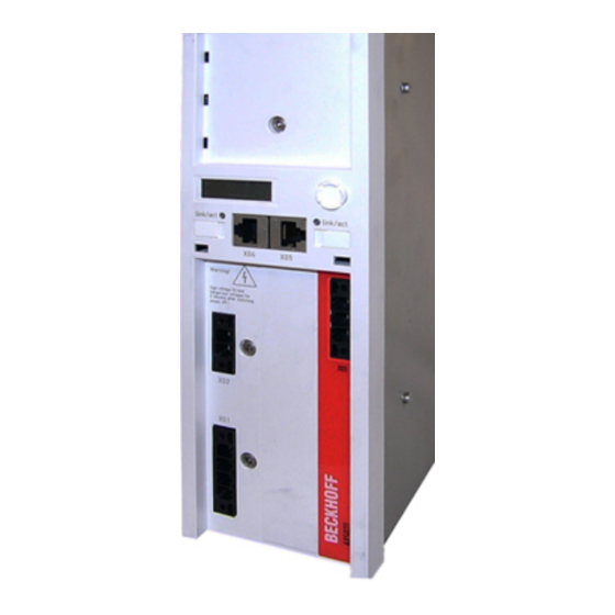
Page 5: Product Overview
Height without connector 274 mm Depth without connector / accessories 232 mm Cable duct >2,5 >277,6 AX5021 AX5206 Control cabinet door Mounting plate contuctible (zinced) 277,6 (Incl. plug and cable for feedback) AX5021 Cable duct AX5000 Brake module AX5021 Version: 1.3... -
Page 6: General Overview
Please refer to the servo drive ‘Startup’ manual for the pin assignments of the remaining inputs and outputs. Temperature rise in the external brake resistor The temperature rise of the external brake resistor should be monitored continuously via temperature contacts (1) and (2). Note Version: 1.3 AX5000 Brake module AX5021... -
Page 7: Electrical Connection (Example)
If the drive system is disconnected from the mains due to a mains failure, all axes of the drive system make uncontrolled movements. Take suitable measures to ensure than no CAUTION persons are endangered during this time. Vertical axes are particularly dangerous. AX5000 Brake module AX5021 Version: 1.3... -
Page 8: Integration Into Twincat
DC link. In a DC link connection the energy could be stored, since the DC link of all linked devices would be loaded first, before the energy in the brake resistors would be converted to heat. Version: 1.3 AX5000 Brake module AX5021... -
Page 9: Operation Modes Of The Ax5021
Product overview 2.8.2 Operation modes of the AX5021 It can be assumed that a brake module is used only if the brake energy cannot be dissipated despite a DC link system and internal brake resistors. The brake module can be operated in two different operation modes, which have a direct influence on the energy management. -
Page 10: Braking Power Diagnosis
The diagnostics should cover the whole system. If not enough reserve capacity is available, an external brake resistor with a higher output should be selected. If the performance limit is still reached, several AX5021 may be used. Energy balance The energy balance is affected positively whenever an axis requires energy and another axis produces generative energy (braking energy).
Need help?
Do you have a question about the AX5021 and is the answer not in the manual?
Questions and answers