Advertisement
Electronic circulator pump operating manual:
CAUTION This operating manual is the primary basis for the
equipment's sale contract. Non-observance of the recommendations
listed in this manual will result in a breach of this contract and will
invalidate any claims made by the user relating to the equipment's failure
resulting from its inappropriate use.
CAUTION Non-observance of recommendations listed in this
operating manual may result in personal injuries or damage to
units where the equipment is installed, the environment or the
pump itself.
CAUTION! Children and persons with reduced physical,
sensory or mental capabilities must not use this equipment;
also persons with no experience or knowledge of the product
unless under the supervision or in accordance with the equipment's
operating manual and instructed by a person responsible for their safety.
Children must not play with this equipment.
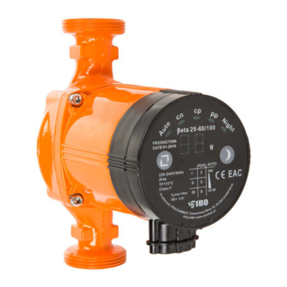
BETA 25-60
CAUTION Prior to operation, please read this operating
manual. Due to safety reasons, the use of this equipment
requires a thorough knowledge of this operating manual.
1
Advertisement
Table of Contents

Subscribe to Our Youtube Channel
Summary of Contents for IBO BETA 25-60
- Page 1 Electronic circulator pump operating manual: BETA 25-60 CAUTION Prior to operation, please read this operating manual. Due to safety reasons, the use of this equipment requires a thorough knowledge of this operating manual. CAUTION This operating manual is the primary basis for the equipment’s sale contract.
- Page 2 APPLICATION: The pumps which this operating manual applies to are used to enforce circulation in central heating installations with constant or variable flows, where the heating medium temperature does not exceed 110 C and the installation pressure does not exceed 1Mpa (1 000 000Pa). The maximum ambient temperature in the pump installation area must not exceed 40 C and the relative humidity must be less than 90%.
-
Page 3: Installation
INSTALLATION: Prior to any installation works, the power supply must always be disconnected. It also must be secured to prevent accidental reconnections. The pump can be connected after all the installation works are carried out on the pipework which will form a part of the installation with the pump. It must be remembered that welding or soldering works can introduce mechanical impurities into the pipework. -
Page 4: Electrical Connection
The arrow moulded on the body shows the direction of water flow. The pump should be installed in such a way that the junction box with the control box is at the top, on the body of the motor. This will prevent water from getting inside the junction box if the installation is not leaktight. -
Page 5: Operating Mode
PUMP OPERATION CONTROL: On the pump start-up, the electricity consumption meter’s display will display the current power consumption level of the pump. If two horizontal bars „- - „ are displayed, it will signify that the pump is blocked. The pump should be disconnected from the electrical network, it should be unblocked (failure repaired) and switched on again. - Page 6 RECOMMENDED SETTINGS FOR DIFFERENT CENTRAL HEATING SYSTEMS: If a house has a two-pipe heating system, where one pipe is a supply pipe to all the radiators in a loop and the second parallel pipe is used to receive the cooled water from the radiators, the most economic solution is to select the AUTO function.
-
Page 7: Night Mode
only after passing through all the radiators in a loop it is taken to the boiler, the most economic setting is the lower setting from PP proportional-pressure curve. Optionally, a higher setting from PP proportional-pressure curve can also be selected. 3) The optimum choice for under floor heating is AUTO or optionally a higher or a lower CP constant-pressure curve setting. -
Page 8: Storage And Transport
For the pump to operate correctly, there must be a minimum inlet pressure of the heating medium (water) on the suction side of the pump. The minimum inlet pressure of the medium is dependent on the temperature of the medium. The higher the temperature, the higher the inlet pressure of the heating medium on the suction side of the pump should be. - Page 9 FAULT IDENTIFICATION AND RECOMMENDED SOLUTIONS: Fault: Possible cause: Remedy: The pump does not Electricity supply failure Check if the pump’s electrical plug is run. The panel does correctly inserted into the socket. display Check fuses at home and any other information.


Need help?
Do you have a question about the BETA 25-60 and is the answer not in the manual?
Questions and answers