Table of Contents
Advertisement
Quick Links
Advertisement
Table of Contents

Related Manuals for SIG EDGE 540T


Summary of Contents for SIG EDGE 540T
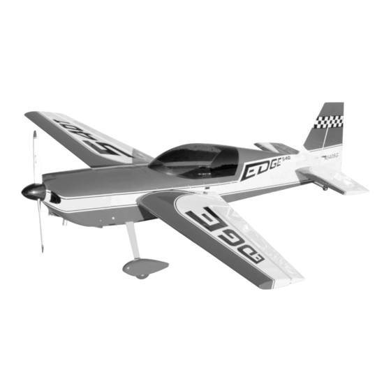
- Page 1 A S S E M B L Y M A N U A L KIT NO. SIGRC100ARF...
-
Page 2: Table Of Contents
SIG EDGE 540T ARF ASSEMBLY MANUAL Table of Contents: Introduction ............................1 Specifications............................1 Items Required To Complete Kit......................1 Radio Equipment System Choice......................2 Receivers And Battery Packs ......................2 Servos..............................2 Servo Output Arms ..........................2 Servo Extensions & Y-Harnesses ......................2 On/Off Switches...........................2 Engine Selection..........................3 Covering ..............................3... -
Page 3: Introduction
Most modelers that we know, who fly giant scale models, use a dedicated trailer for this purpose. Let's face it, the SIG Edge 540T ARF is simply not going to fit in INTRODUCTION the back seat of your car! Therefore, serious consideration has to Congratulations on the purchase of your SIG Edge 540T ARF kit. -
Page 4: Radio Equipment System Choice
Radio Equipment System Choice aftermarket heavy-duty servo arms, you can purchase good The SIG Edge 540T ARF is a giant scale radio control aircraft quality arms, such as the SWB products, for your specific servos. that benefits greatly from the use of a sophisticated computer... -
Page 5: Engine Selection
If you choose to power your Edge 540T with a different brand of Also be aware that the aft top turtledeck on the Edge 540T ARF gas engine, then we suggest using engines in the 95 to 110cc model is a composite of shaped white foam, sheeted with range. -
Page 6: Kit Contents
*WHEEL NOTE: The two 4.3" dia. main wheels provided with the 1 Bag 1 each Throttle Servo Mounting Tray - 2.75mm Edge 540T ARF kit are of high quality, designed to be as light as Plywood possible, with a weight of only 44.5 grams per wheel! Our reason for 2 each M4 x 20mm Hex Head Bolts - Rear Wing using these wheels has everything to do with weight. -
Page 7: Individual Part Inspection
Use a good Pre-Assembly: quality cleaning solution, such as SIG Pure Magic Model Airplane The Edge 540T ARF is a very large model airplane that obviously Cleaner, Windex ® , or Fantastic ®... -
Page 8: Assembly
The graphic is now adhered permanently in place. To do this, we With everything now pre-fitted, disassemble the wing panels from suggest using a plastic squeegee. The SIG 4" plastic Epoxy the fuselage and remove the main wing tube. Set the tube aside Spreader squeegee - P/N SH678 - is perfect for this purpose. -
Page 9: Hinging Flight Surfaces
Further, it is imperative that each hinge be securely glued in place. Remove the tubes from the stab half. The Edge 540T ARF kit includes excellent Super Hinge Point hinges. These are high quality, very strong, and easy to install. -
Page 10: Hinge Gap Sealing
Again, check the hinge gap for the closest possible fit, while 3) The strip is now cut to the correct length for the aileron hinge maintaining full movement ability. Allow the glue to cure for at least line. This should be 35-3/4". The completed strip will now be 6 hours. - Page 11 Note: For clarification purposes in this manual, we define a left The servo is now positioned into the servo bay, with its output and a right control horn by simply looking straight down on the spline forward, toward the leading edge of the wing panel. Using horn, as shown.
-
Page 12: Elevator Servo Installation
be aligned to the servo at 90 and should both be in line and onto the hardwood mounting rails. Remove the servo from the parallel with each other. Select two of the pre-assembled aileron stab. linkages. On both pushrods, thread the two lock nuts all the way in toward each other, leaving the maximum amount of threads 2) Pre-drill small guide holes for the servo. -
Page 13: Landing Gear & Wheel Pant Assembly
5) Use your transmitter and receiver to now check and adjust the this process with the remaining wheel and wheel pant. Once you proper movement of the elevator halves. The pushrod clevis are satisfied, remove the M3 x 15mm pant mounting bolts and the locking nuts and clevis safety springs do not need to be tightened wheel pants. -
Page 14: Mounting The Tail Wheel
Measure forward 7/8" from the tip of the fin hinge line, mark this g) The Landing Gear Hatch Cover is now installed over the mounted landing gear using two T3 x 16mm PWA screws. Note location on the centerline. This point is the location for the that both the access and clearance holes are already provided in rearmost T3 x 16mm PWA tail wheel assembly mounting screw. -
Page 15: Mounting The Engine
The firewall on the Edge 540T ARF has been factory-built with 2 left and right arms spaced equally on each side. Mark the of right thrust. The firewall has also been accurately marked with locations of the two mounting holes onto the rudder with a vertical and horizontal centerlines. -
Page 16: Mounting The Cowl
sparkplug wires to each cylinder head and in providing good wiring front edge of the fuselage side, at each of these marks. At the proximity for the power and timing extension leads. bottom line, measure back 1/2" from the front edge of the tape and make a mark. -
Page 17: Fitting The Cowl
Fuel Tank Assembly: The fuel tank supplied with the Edge 540T ARF kit has an 800cc (27.05 oz.) capacity and includes a gasoline-compatible fuel stopper. If you wish, commercially available fuel tanks of larger capacities may also be used. -
Page 18: Fuel Tank Installation
The kit fuel tank also includes two small nylon cable ties. We used one of these over the rubber stopper, pulling it tight to secure the stopper firmly in place to the tank. The remaining cable tie can be used to hold the carb and overflow lines together, as they route forward to the front of the fuselage (if you are like us, you will want to use more of these cable ties to organize the fuel tubing and servo extensions. -
Page 19: Rudder Servo & Pull-Pull Installation
2-56 or 4-40 nylon pushrod system (not included). Note that the kit also includes a single 1.8 x 300mm The Edge 540T was designed with control horn mounting locations metal pushrod and clevis. This can be used, if desired, when that approximates the mean aerodynamic cord of rudder itself. -
Page 20: Receiver & Battery Pack Installation
Receiver & Battery Pack Installation: The receiver(s) and battery pack(s) were mounted on the built in radio tray in the fuselage of our Edge 540T models. We made simple mounting platforms for our battery packs, using lite-ply. We did not mount these pack mounts until after we had conducted our Center of Gravity routine, described later in this manual. -
Page 21: Mounting The Propeller & Spinner
Choose the spinner assembly that you wish to use on your Edge and install it according to the manufacturer's instructions. For reference, we have been flying our own Edge 540T ARF Center of Gravity (CG): models with a 29% Center of Gravity. This CG location allows us... -
Page 22: Flight Surface Movements & Exponential Inputs
Nose-Heavy Condition: Low Rate Movements: In this case, we like to start by suspending the model at the desired Elevators 1-1/4" Up, 1-1/4" Down (10° Up, 10° Down) with -25% Expo CG location, allowing the fuselage to seek its attitude. We then Ailerons 1-9/16"... -
Page 23: Flying
The SIG Edge 540T is actually quite easy to take off. However, it is a tail dragger and coordinated rudder input will be needed It should come as no surprise that you should NEVER fly this during the take-off run to manage torque. -
Page 24: Aerobatics
Ok, assuming that you've gotten to this point, you're probably in the high rate position. The elevators and rudder should be in low ready to see what your Edge 540T is capable of. Remember what rate positions, with the low to moderate entry speed. A word of we had to say earlier about throttle management and aerobatics, caution is in order here. -
Page 25: Referenced Manufacturer Information
SIG MANUFACTURING COMPANY, INC. is committed to your toys! Because of the speeds that airplanes must achieve in order success in both assembling and flying the EDGE 540T ARF. to fly, they are capable of causing serious bodily harm and Should you encounter any problem building this kit or discover any property damage if they crash. - Page 26 EXTRA 540T LOG BOOK Date of first flight: Comments:...
- Page 27 EXTRA 540T LOG BOOK Date of first flight: Comments:...
- Page 28 First Place Engines machines all other major components from billet aluminum and bar steel stock. It’s a gas engine designed and produced by modelers for modelers. The perfect power plant for the SIG Edge 540T ARF! Specifications: Size: 6.8 cubic inches (111 cc)
Need help?
Do you have a question about the EDGE 540T and is the answer not in the manual?
Questions and answers