
Related Manuals for Keysight Technologies E1465A


Summary of Contents for Keysight Technologies E1465A
- Page 1 75000 Series C Service Manual Keysight E1465A/E1466A/ E1467A Relay Matrix Switch Modules...
- Page 3 WITHOUT NOTICE, IN FUTURE EDI- without prior agreement and written con- www.keysight.com/find/E1466A TIONS. FURTHER, TO THE MAXIMUM sent from Keysight Technologies, Inc. as EXTENT PERMITTED BY APPLICABLE (product-specific information and sup- governed by United States and interna- LAW, KEYSIGHT DISCLAIMS ALL WAR- port, software and documentation tional copyright laws.
- Page 4 If necessary, return instrument chassis and cover must be safe operating conditions, modules the product to a Keysight Technologies connected to an electrical ground to should not be operated beyond the full Sales and Service Office for service and minimize shock hazard.
- Page 5 Safety Symbols A CAUTION denotes a hazard. It calls attention to an operating pro- cedure or practice, that, if not cor- rectly performed or adhered to could result in damage to the product or loss of important data. Do not proceed beyond a CAUTION notice until the indicated condi- tions are fully understood and met.
-
Page 7: Table Of Contents
Test Accuracy Ratio (TAR)........41 Keysight E1465A/E1466A/E1467A Relay Matrix Service Manual... - Page 8 Post-Repair Safety Checks ........78 Component Locators and Schematic Diagrams ......78 Keysight E1465A/E1466A/E1467A Relay Matrix Service Manual...
-
Page 9: General Information
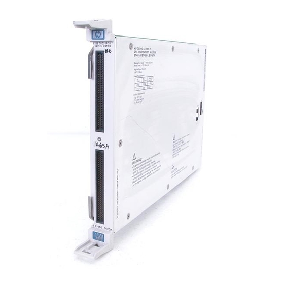
Introduction This manual contains information required to test, troubleshoot, and repair the Keysight E1465A 16 x 16 Relay Matrix, the E1466A 4 X 64 Relay Matrix, and the E1467A 8 X 32 Relay Matrix (see Figure 1-1). Figure 1- 1 Keysight E1465A/E1466A/E1467A Matrixes... -
Page 10: Relay Life
However, this method requires knowledge of the applied load and life specifications for the applied load. For the Keysight E1465A/E1466A/E1467A maximum relay life is specified at 107 operations with no load and 105 operations at the maximum rated load. -
Page 11: Safety Considerations
Warnings and Cautions This section contains WARNINGS which must be followed for your protection and CAUTIONS which must be followed to avoid damage to the equipment when performing instrument maintenance or repair. Keysight E1465A/E1466A/E1467A Relay Matrix Service Manual... - Page 12 USE PROPER FUSES. For continued protection against fire hazard, replace the line fuses only with fuses of the same current rating and type (such as normal blow, time delay, etc.). Do not use repaired fuses or short-circuited fuseholders. Keysight E1465A/E1466A/E1467A Relay Matrix Service Manual...
- Page 13 30 W or 62.5 VA (ac Resistive Load). STATIC ELECTRICITY. Static electricity is a major cause of component failure. To prevent damage to the electrical components in the matrix, observe anti-static techniques whenever working on the device. Keysight E1465A/E1466A/E1467A Relay Matrix Service Manual...
-
Page 14: Inspection/Shipping
Use the steps in Figure 1-2 as guidelines to perform initial inspection of one of the modules. Verification Tests are optional. To avoid possible hazardous electrical shock, do not perform electrical tests if there are signs of shipping damage to the shipping container or to the instrument. Keysight E1465A/E1466A/E1467A Relay Matrix Service Manual... - Page 15 Inspection/Shipping General Information Figure 1- 2 Initial (Incoming) Inspection Guidelines Keysight E1465A/E1466A/E1467A Relay Matrix Service Manual...
-
Page 16: Shipping Guidelines
Figure 1- 3 Packaging/Shipping Guidelines * We recommend that you use the same shipping materials as those used in factory packaging (available from Keysight Technologies). For other (commercially-available) shipping materials, use a double-wall carton with minimum 2.4 MPa (350 psi) test. -
Page 17: Environment
Figure 1-1). The component module contains 256 latching relays implemented as four 4 X 16 submatrixes. The terminal ,modules convert these submatrixes into a 16 X 16 (Keysight E1465A), 4 X 64 (Keysight E1466A), or 8 X 32 (Keysight E1467A) matrix. The terminal module matrixes are two-wire crosspoint switching (HI and LO). -
Page 18: Matrix Options
O,P, T Digital Multimeter Keysight 3458A or 2-wire ohms (up to 1 GΩ ) Keysight 34401A * F = Functional Verification Tests, O = Operation Verification Tests, P = Performance Verification Tests, T = Troubleshooting Keysight E1465A/E1466A/E1467A Relay Matrix Service Manual... -
Page 19: Verification Tests
Verification Tests Introduction The three levels of test procedures described in this chapter are used to verify that the Keysight E1465A/E1466A/E1467A matrix module: – is fully functional (Functional Verification) – meets selected testable specifications (Operation Verification) – meets all testable specifications (Performance Verification) Test Conditions/ Procedures See Table 1-1 for test equipment requirements. -
Page 20: Matrix Module Functional Verification
Matrix Module Functional Verification Matrix Module Functional Verification The Functional Verification Test for the Keysight E1465A/E1466A/E1467A matrix modules consists of sending the *TST? command and checking the response. This test can be used at any time to verify that the device is connected properly and is responding to basic commands. -
Page 21: Performance Verification
Wiring the Test Fixture A test fixture is required for the performance verification tests. Figure 2-1 shows typical connections using an Keysight E1465A terminal module for the test fixture. Figure 2-2 shows typical connections using an Keysight E1466A terminal module for the test fixture. Figure 2-3 shows typical connections using an Keysight E1467A terminal module for the test fixture. - Page 22 Verification Tests Performance Verification Figure 2- 1 Keysight E1465A Test Fixture Figure 2- 2 Keysight E1466A Test Fixture Keysight E1465A/E1466A/E1467A Relay Matrix Service Manual...
-
Page 23: Test 2-1: Closed Channel Resistance Test
Column HI to Row HI Measurements 1 Make Hardware Connections – Turn mainframe power OFF – Connect DMM leads as shown in Figure 2-4 – Set DMM to measure 4-wire Ohms – Turn mainframe power ON Keysight E1465A/E1466A/E1467A Relay Matrix Service Manual... - Page 24 – Send CLOS (@nn0000) to close column 0 row 0, where nn = card # (typically 01) – Trigger the DMM with TRIG SGL and note reading – Send OPEN (@nn0000) to open column 0 row 0, where nn = card # (typically 01) Keysight E1465A/E1466A/E1467A Relay Matrix Service Manual...
- Page 25 – • Use CLOS (@nn00cc) and OPEN (@nn00cc), where nn = card # and cc= column # (omit leading zeroes in nn) For E1465A use column numbers 01 through 15 For E1466A use column numbers 01 through 63 For E1467A use column numbers 01 through 31 5 Repeat for all Rows –...
- Page 26 Use this list in Chapter 4 — Service when troubleshooting a failing relay. RE-SAVE "CLOS_TEST" 20ASSIGN @Dmm TO 722 30ASSIGN @Sw TO 70915 40DISP CHR$(129) Keysight E1465A/E1466A/E1467A Relay Matrix Service Manual...
- Page 27 240 CASE "1" 250Row=15 260Col=15 270 CASE "4" 280Row=3 290Col=63 300 CASE "8" 310Row=7 320Col=31 330 CASE ELSE 340PRINT "Wrong card type detected ";A$ 350STOP 360 END SELECT 370 FOR T=0 TO 1 380CLEAR SCREEN Keysight E1465A/E1466A/E1467A Relay Matrix Service Manual...
- Page 28 590PRINT "Stuck relay found" 600PRINT "Correct the problem and re-run test" 610STOP 620END IF 630! Begin contact resistance test 640FOR J=0 TO Row 650IF J<10 THEN 660Row$=Ph$&VAL$(J) 670ELSE 680Row$=VAL$(J) 690END IF 700FOR K=0 TO Col Keysight E1465A/E1466A/E1467A Relay Matrix Service Manual...
- Page 29 950END IF 960OUTPUT @Sw;"OPEN (@"&Cc$&Row$&Col$&")" 970NEXT K 980NEXT J 990CLEAR SCREEN 1000PRINT "Measurements complete for Row ";Path$(T); " To Column ";Path$(T) 1010IF T=0 THEN 1020DISP "Press continue for Row ";Path$(T+1); " to Column ";Path$(T+1) 1030ELSE Keysight E1465A/E1466A/E1467A Relay Matrix Service Manual...
- Page 30 • • • • • • • Row 7 to Col 29 .4127 Ohms .4007 Ohms Row 7 to Col 30 .4002 Ohms .4111 Ohms Row 7 to Col 31 .4047 Ohms .4245 Ohms Keysight E1465A/E1466A/E1467A Relay Matrix Service Manual...
-
Page 31: Test 2-2: Dc Isolation Test
3 Send CLOS (@10000:1rrcc) to the matrix to close all relays where rr = highest row number and cc = highest column number For E1465A, rr = 15 and cc = 15 For E1466A, rr = 03 and cc = 63... - Page 32 3 Send CLOS (@10000:1rrcc) to the matrix to close all relays where rr = highest row number and cc = highest column number For E1465A, rr = 15 and cc = 15 For E1466A, rr = 03 and cc = 63...
- Page 33 3 Send CLOS (@10000:1rrcc) to the matrix to close all relays where rr = highest row number and cc = highest column number – For E1465A, rr = 15 and cc = 15 For E1466A, rr = 03 and cc = 63...
- Page 34 Figure 2- 8 LO to Chassis Isolation Test Connections 5 Record the DMM reading in Table 2-1 (LO to Chassis) RE-SAVE "DC_ISOL" 20ASSIGN @Dmm TO 722 30ASSIGN @Sw TO 70915 40DISP CHR$(129) 50DIM Cc$[2],Row$[2],Col$[2],A$[255],Conn$(2)[9],Value(2) Keysight E1465A/E1466A/E1467A Relay Matrix Service Manual...
- Page 35 CASE "4" 270Row$="03" 280Col$="63" CASE "8" 300Row$="07" 310Col$="31" CASE ELSE 330PRINT "Wrong card type detected: ";A$ 340STOP END SELECT CLEAR SCREEN Measure DC isolation HI to LO, HI to Chassis, and LO to Chassis Keysight E1465A/E1466A/E1467A Relay Matrix Service Manual...
- Page 36 ";Conn$(1) PRINT TABXY(1,4)," 2. Connect DMM Input LO lead to ";Conn$(2) DISP "Press Continue when connections are complete" PAUSE CLEAR SCREEN OUTPUT @Dmm;"TRIG SGL" ENTER @Dmm;Value(2) OUTPUT @Sw;"OPEN (@"&Cc$&"0000:"&Cc$&Row$&Col$&")" PRINT "DC Isolation Tests Complete" Keysight E1465A/E1466A/E1467A Relay Matrix Service Manual...
- Page 37 This example performs DC Isolation Tests for HI to LO, HI to Chassis, and LO to chassis Typical Result DC Isolation Tests HI to LO (Ohms) 1E+38 HI to Chassis (Ohms) 1E+38 LO to Chassis (Ohms) 1E+38 Keysight E1465A/E1466A/E1467A Relay Matrix Service Manual...
-
Page 38: Performance Test Record
Test Limits Test limits are defined for Closed Channel Resistance Test and DC Isolation Test using the specifications in Appendix A of the Keysight E1465A/E1466A/ E1467A Relay Matrix Switch Modules User’s Manual. The specifications are single-sided, (i.e., there is an upper limit or a lower limit, but not both). In the Performance Test Record, the Minimum or Maximum column will be blank. -
Page 39: Test Accuracy Ratio (Tar)
Address __________________________________ Date _________________________ Customer ________________________________ City/State ______________________________________________________________ Tested by _______________________________________________________________ Phone ___________________________ Special Notes: ________________________________________________________________________ ________________________________________________________________________ ________________________________________________________________________ ________________________________________________________________________ ________________________________________________________________________ ________________________________________________________________________ Test Equipment Record Model No. Trace No. Test Equipment Used: Description Cal Due Date Keysight E1465A/E1466A/E1467A Relay Matrix Service Manual... - Page 40 9.050E-5 NA NA NA NA R01 C13 R00 C29 R00 C29 9.050E-5 R01 C14 R00 C30 R00 C30 9.050E-5 R01 C15 R00 C31 R00 C31 9.050E-5 *Single-sided specification - Minimum value does not apply Keysight E1465A/E1466A/E1467A Relay Matrix Service Manual...
- Page 41 R00 C60 R01 C28 9.050E-5 R03 C13 R00 C61 R01 C29 9.050E-5 R03 C14 R00 C62 R01 C30 9.050E-5 R03 C15 R00 C63 R01 C31 9.050E-5 *Single-sided specification - Minimum value does not apply Keysight E1465A/E1466A/E1467A Relay Matrix Service Manual...
- Page 42 R01 C28 R02 C28 9.050E-5 R05 C13 R01 C29 R02 C29 9.050E-5 R05 C14 R01 C30 R02 C30 9.050E-5 R01 C31 R05 C15 R02 C31 9.050E-5 *Single-sided specification - Minimum value does not apply Keysight E1465A/E1466A/E1467A Relay Matrix Service Manual...
- Page 43 R01 C60 R03 C28 9.050E-5 R07 C13 R01 C61 R03 C29 9.050E-5 R07 C14 R01 C62 R03 C30 9.050E-5 R07 C15 R01 C63 R03 C31 9.050E-5 *Single-sided specification - Minimum value does not apply Keysight E1465A/E1466A/E1467A Relay Matrix Service Manual...
- Page 44 R02 C28 R04 C28 9.050E-5 R09 C13 R02 C29 R04 C29 9.050E-5 R09 C14 R02 C30 R04 C30 9.050E-5 R09 C15 R02 C31 R04 C31 9.050E-5 *Single-sided specification - Minimum value does not apply Keysight E1465A/E1466A/E1467A Relay Matrix Service Manual...
- Page 45 R05 C28 9.050E-5 R11 C12 R02 C61 R05 C29 9.050E-5 R11 C13 R02 C62 R05 C30 9.050E-5 R11 C14 R02 C63 R05 C31 9.050E-5 R11 C15 *Single-sided specification - Minimum value does not apply Keysight E1465A/E1466A/E1467A Relay Matrix Service Manual...
- Page 46 R06 C28 9.050E-5 R13 C12 R03 C29 R06 C29 9.050E-5 R13 C13 R03 C30 R06 C30 9.050E-5 R13 C14 R03 C31 R06 C31 9.050E-5 R13 C15 *Single-sided specification - Minimum value does not apply Keysight E1465A/E1466A/E1467A Relay Matrix Service Manual...
- Page 47 R07 C28 9.050E-5 R15 C12 R03 C61 R07 C29 9.050E-5 R15 C13 R03 C62 R07 C30 9.050E-5 R15 C14 R03 C63 R07 C31 9.050E-5 R15 C15 *Single-sided specification - Minimum value does not apply Keysight E1465A/E1466A/E1467A Relay Matrix Service Manual...
- Page 48 Uncert Ratio (TAR) Test 2-2 DC Isolation (values in ohms) 1.2E9 6.01E6 HI to LO 1.2E9 6.01E6 HI to Chassis 1.2E9 6.01E6 LO to Chassis * Single-sided specification - Maximum value does not apply Keysight E1465A/E1466A/E1467A Relay Matrix Service Manual...
-
Page 49: Replaceable Parts
This chapter contains information for ordering replaceable parts for the Keysight E1465A/E1466A/E1467A Relay Matrixes. Ordering Information To order a part listed in this chapter, specify the Keysight Technologies part number and the quantity required. Send the order to your nearest Keysight Technologies Sales and Support Office. -
Page 50: Replaceable Parts Lists
E1466-00602 SHD2 SHIELD-BOTTOM † NOTE: For modules with serial numbers below 3126A00445 (E1465A), 3126A01090 (E1466A), or 3126A01109 (E1467A), the following parts must be used for replacement (see inset in figure 3-1). E1466-66201 MOD - HI DENSITY MATRIX (See Figure 3-1) - Page 51 0490-1782 RELAY 2C 12VDC-COIL 1A 250VDC K400-K415 0490-1782 RELAY 2C 12VDC-COIL 1A 250VDC K500-K515 0490-1782 RELAY 2C 12VDC-COIL 1A 250VDC K600-K615 0490-1782 RELAY 2C 12VDC-COIL 1A 250VDC K700-K715 0490-1782 RELAY 2C 12VDC-COIL 1A 250VDC Keysight E1465A/E1466A/E1467A Relay Matrix Service Manual...
- Page 52 1820-3975 IC DRIVER CMOS/HC LINE OCTL U106 1820-3631 IC COMPARATOR CMOS/HCT MAGNITUDE 8-BIT IC LATCH CMOS/HCT TRANSPARENT U107 1820-4147 OCTL U108-U109 1820-3714 IC TRANSCEIVER TTL/ALS BUS OCTL U110 1820-3079 IC DECODER CMOS/HC BIN 3-TO-8-LINE Keysight E1465A/E1466A/E1467A Relay Matrix Service Manual...
- Page 53 IC DRIVER CMOS/HCT LINE OCTL U305-U308 1820-4599 IC-INTERFACE DRIVER U401 1858-0069 TRANSISTOR ARRAY 18-PIN PLASTIC DIP U402 1820-6475 IC FIFO CMOS ASYNCHRO 4608-BIT U403 1820-5424 IC DRIVER CMOS/HCT LINE OCTL U404-U407 1820-4599 IC-INTERFACE DRIVER Keysight E1465A/E1466A/E1467A Relay Matrix Service Manual...
- Page 54 Replaceable Parts Replaceable Parts Lists Figure 3-1 Component Assembly Replaceable Parts Keysight E1465A/E1466A/E1467A Relay Matrix Service Manual...
- Page 55 Case Assembly - Terminal (see Figure 3-2) E1400-45103 Top Lever E1400-45104 Bottom Lever 1460-2552 Torsion Spring - Left Hand Wound 1460-2553 Torsion Spring - Right Hand Wound 1390-1027 Receptical Quick Fastener Figure 3-2 Terminal Case Assembly Replaceable Parts Keysight E1465A/E1466A/E1467A Relay Matrix Service Manual...
- Page 56 CASE TERMINAL BLK ASSY (See Figure 3-3) 03852-01201 CLAMP 03852-86701 PAD-CLAMP 0515-2109 SCREW-MACHINE 10-24 .625-IN-LG PAN-HD-SLT FASTENER-CAPTIVE SCREW M2.5 X 0.45 1390-0846 CLAMP STRAIN RELIEF E1300-01202 TERMINAL HOUSING-BOTTOM E1400-44104 TERMINAL HOUSING-TOP E1400-44105 Figure 3-3 Terminal Case Assembly Replaceable Parts Keysight E1465A/E1466A/E1467A Relay Matrix Service Manual...
- Page 57 Replaceable Parts Lists Replaceable Parts Table 3-4 Keysight E1465A Terminal Module Replaceable Parts Reference Keysight Part Part Description Designator Number E1465-66510 TERMINAL CARD 16X16 MATRIX (See Figure 3-4) 1252-1593 CONNECTOR-POST TYPE 2.54-PIN-SPCG 96-CONTACT P1-P2 TERMINAL BLOCK 8 POS. POLYESTER TB1-TB16...
- Page 58 Replaceable Parts Replaceable Parts Lists Figure 3-4 Keysight E1465A Terminal Module Figure 3-5 Keysight E1466A Terminal Module Keysight E1465A/E1466A/E1467A Relay Matrix Service Manual...
- Page 59 RP .....resistor pack CVR...cover RT .....thermistor probe F ....fuse SCR ..screw J ....electrical connector (jack) SHD ..shield JM .....jumper SW ....switch K ....relay TB....terminal block (terminal module) MP .....mechanical part U....integrated circuit P ....electrical connector (plug) Keysight E1465A/E1466A/E1467A Relay Matrix Service Manual...
- Page 60 Replaceable Parts Replaceable Parts Lists Keysight E1465A/E1466A/E1467A Relay Matrix Service Manual...
-
Page 61: Service
Keysight E1465A/E1466A/E1467A Relay Matrix Service Manual Service Introduction This chapter contains service information for the Keysight E1465A/E1466A/ E1467A matrix modules, including troubleshooting techniques and repair/maintenance guidelines. Do not perform any of the service procedures shown unless you are a qualified, service-trained technician, and have read the WARNINGS and CAUTIONS in Chapter 1. -
Page 62: Troubleshooting
See Chapter 3 — Replaceable Parts and the component locators at the back of this manual for descriptions and locations of Keysight E1465A/E1466A/ E1467A matrix modules replaceable parts. Identifying the Problem Table 4-1 lists some common problems, along with symptoms and possible solutions. -
Page 63: Testing The Assembly
Figure 4-1 shows a simplified diagram of the relay driver and decoder circuits. As shown in the figure, the relays on the component assembly are arranged into 16 banks of 16 relays. Each bank of relays switches 16 columns to a single row. Keysight E1465A/E1466A/E1467A Relay Matrix Service Manual... - Page 64 The relay contacts are arranged into four 4 X 16 submatrixes. These submatrixes are then arranged into the appropriate matrixes by each terminal module. The latching relays are double pole and switch both HI and LO lines. Figure 4-1 Relay Driver/Decoder Simplified Diagram Keysight E1465A/E1466A/E1467A Relay Matrix Service Manual...
-
Page 65: Matching Relays To Channels
K812 U406 U406 U406 R01 C13 R00 C29 R00 C29 K113 K413 K813 R01 C14 R00 C30 R00 C30 K114 K414 K814 U407 U407 U407 R01 C15 R00 C31 R00 C31 K115 K415 K815 Keysight E1465A/E1466A/E1467A Relay Matrix Service Manual... - Page 66 K912 U406 U406 U406 R03 C13 R00 C61 R01 C29 K313 K1213 K913 R03 C14 R00 C62 R01 C30 K314 K1214 K914 U407 U407 U407 R03 C15 R00 C63 R01 C31 K315 K1215 K915 Keysight E1465A/E1466A/E1467A Relay Matrix Service Manual...
- Page 67 K512 U406 U406 U406 R05 C13 R01 C29 R02 C29 K1013 K513 K513 R05 C14 R01 C30 R02 C30 K1014 K514 K514 U407 U407 U407 R05 C15 R01 C31 R02 C31 K1015 K515 K515 Keysight E1465A/E1466A/E1467A Relay Matrix Service Manual...
- Page 68 K1112 U406 U406 U406 R07 C13 R01 C61 R03 C29 K713 K1313 K1113 R07 C14 R01 C62 R03 C30 K714 K1314 K1114 U407 U407 U407 R07 C15 R01 C63 R03 C31 K715 K1315 K1115 Keysight E1465A/E1466A/E1467A Relay Matrix Service Manual...
- Page 69 K1212 U406 U406 U406 R09 C13 R02 C29 R04 C29 K913 K613 K1213 R09 C14 R02 C30 R04 C30 K914 K614 K1214 U407 U407 U407 R09 C15 R02 C31 R04 C31 K915 K615 K1215 Keysight E1465A/E1466A/E1467A Relay Matrix Service Manual...
- Page 70 K1312 U406 U406 U406 R02 C61 R05 C29 R11 C13 K1113 K1413 K1313 R02 C62 R05 C30 R11 C14 K1114 K1414 K1314 U407 U407 U407 R02 C63 R05 C31 R11 C15 K1115 K1415 K1315 Keysight E1465A/E1466A/E1467A Relay Matrix Service Manual...
- Page 71 K1412 U406 U406 U406 R03 C29 R06 C29 R13 C13 K1313 K713 K1413 R03 C30 R06 C30 R13 C14 K1314 K714 K1414 U407 U407 U407 R03 C31 R06 C31 R13 C15 K1315 K715 K1415 Keysight E1465A/E1466A/E1467A Relay Matrix Service Manual...
- Page 72 K1512 U406 U406 U406 R03 C61 R07 C29 R15 C13 K1513 K1513 K1513 R03 C62 R07 C30 R15 C14 K1514 K1514 K1514 U407 U407 U407 R03 C63 R07 C31 R15 C15 K1515 K1515 K1515 Keysight E1465A/E1466A/E1467A Relay Matrix Service Manual...
-
Page 73: Self-Test Error Codes
*nn = card number (with leading zero deleted) Disassembly Use the following procedures to disassemble the Keysight E1465A/E1466A/E1467A matrix modules. For disassembly refer to Figure 4-1. 1 To remove the covers: – Remove the eight T10 Torx screws from the top cover as shown. - Page 74 Service Troubleshooting Figure 4-2 E1465A/E1466A/E1467A Disassembly Keysight E1465A/E1466A/E1467A Relay Matrix Service Manual...
-
Page 75: Repair/ Maintenance Guidelines
– Use a suction device or wooden toothpick to remove solder from component mounting holes. When using a suction device, be sure that the equipment is properly grounded. Keysight E1465A/E1466A/E1467A Relay Matrix Service Manual... -
Page 76: Post-Repair Safety Checks
L-E1466-66501 (1 of 2) E1465A/66A/67A Matrix Switches Component Assembly (Side B) E1466-66501 Schematic E1466-66501 S-E1466-66501 (1 of 13) E1465A/66A/67A Matrix Switches - VXI Interface #1 Diagrams S-E1466-66501 (2 of 13) E1466-66501 E1465A/66A/67A Matrix Switches - VXI Interface #2 S-E1466-66501 (3 of 13) E1466-66501... - Page 78 This information is subject to change without notice. © Keysight Technologies, 2019 Printed in Malaysia Edition 3 October 2019 *E1466-90011* E1466-90011 www.keysight.com...
Need help?
Do you have a question about the E1465A and is the answer not in the manual?
Questions and answers