Table of Contents
Advertisement
Advertisement
Table of Contents

Related Manuals for Keysight Technologies 34950A


Summary of Contents for Keysight Technologies 34950A
- Page 1 Keysight 34950A 64-Bit Digital I/O and Counter Module User’s Guide...
- Page 2 EXPRESS OR IMPLIED, WITH REGARD agreement and written consent from customarily provided to the public. TO THIS MANUAL AND ANY Keysight Technologies as governed by Accordingly, Keysight provides the INFORMATION CONTAINED HEREIN, United States and international Software to U.S. government INCLUDING BUT NOT LIMITED TO THE copyright laws.
-
Page 3: Safety Symbols
Frame or chassis (ground) terminal Standby supply. Unit is not completely disconnected from ac mains when Caution, risk of electric shock switch is off Caution, risk of danger (refer to this manual for specific Warning or Caution information) Keysight 34950A User’s Guide... -
Page 4: Additional Safety Notices
(grounding) conductor or disconnection of the protective earth terminal will cause a potential shock hazard that could result in personal injury. Do Not Operate in an Explosive Atmosphere Do not operate the instrument in the presence of flammable gases or fumes. Keysight 34950A User’s Guide... -
Page 5: Do Not Remove The Instrument Cover
In Case of Damage Instruments that appear damaged or defective should be made inoperative and secured against unintended operation until they can be repaired by qualified service personnel. Keysight 34950A User’s Guide... -
Page 6: Waste Electrical And Electronic Equipment (Weee) Directive 2002/96/Ec
To contact Keysight for sales and technical support, refer to the support links on the following Keysight websites: – www.keysight.com/find/34980a (product-specific information and support, software and documentation updates) – www.keysight.com/find/assist (worldwide contact information for repair and service) Keysight 34950A User’s Guide... -
Page 7: Table Of Contents
........6 34950A 64-Bit Digital I/O Module with Memory and Counter . - Page 8 ........41 Keysight 34950A User’s Guide...
-
Page 9: 34950A 64-Bit Digital I/O Module With Memory And Counter
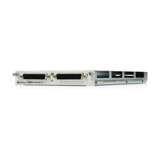
34950A 64-Bit Digital I/O Module with Memory and Counter The 34950A has 64-bits of general-purpose digital I/O grouped in 8-bit channels with programmable polarity, input thresholds, and output levels. The module is segmented into two banks of four 8-bit channels. Each bank has 64 Kb of volatile memory for pattern capture and pattern generation with hardware interrupt capability. -
Page 10: Bank And Channel Assignments
Bank Bank Bit 23 Bit 23 Bit 24 Bit 24 Channel Channel Bit 31 Bit 31 Counter/ 32 Bits 24 Bits Clock Channel Totalizer Gate 20 MHz - 10 Hz Counter/ 32 Bits Channel Totalizer Gate Keysight 34950A User’s Guide... -
Page 11: Electrical Characteristics For Digital I/O Lines
< 5V -4mA < I < -24mA Open Collector: 0V – 5V -4 mA < I < -24mA (< 2V) 215Ω < R < 1 kΩ pullup (> 2V) 215Ω < R < 10 kΩ pullup Keysight 34950A User’s Guide... -
Page 12: Operating Considerations
User’s Guide for detailed environmental operating conditions for the 34980A mainframe and its installed modules. That guidance sets maximum per channel current and power ratings at rated voltage for pollution degree 1 (dry) and pollution degree 2 (possible condensation) conditions, for the Digital I/O module. Keysight 34950A User’s Guide... -
Page 13: Basic Digital I/O Operations
Width and direction of the memory operations are controlled by the width and direction of the first channel on the bank (i.e., 101 or 201). In the SCPI language for the 34950A, BYTE refers to 8-bit operations, WORD refers to 16-bit operations, and LWORd refers to 32-bit operations. -
Page 14: Writing Digital Data
To write digital data, set the channel output parameters using the SOURce commands. For example, sending the following SCPI commands to a Digital I/O module in slot 1 sets a 32-bit channel to use normal polarity, with active drive and a ‘set’ output voltage of 4 volts. Keysight 34950A User’s Guide... - Page 15 CONFigure:DIGital:DATA:WIDTh command. The data written is masked by the configured width so that any extra bytes will be discarded. For example: sending the value 65531 to a byte wide channel will result in the channel discarding the upper byte and outputting 251. Keysight 34950A User’s Guide...
-
Page 16: Channel Width And Polarity, Threshold, Level, And Drive
8 bits will read or written using inverted polarity. Threshold, level, and drive settings all behave in the same manner as the polarity setting described above. Keysight 34950A User’s Guide... -
Page 17: Handshaking
By default, no handshaking is used; data is input or output as the command is executed. The handshake is configured per bank. The 34950A provides a synchronous handshake mode (strobe handshake). You can use this mode with basic input and output operations. You must use this handshake mode to use buffered I/O (see “Buffered I/O Operations”... -
Page 18: Setting The Handshake Line Parameters
The settings for drive mode, output drive level, and input threshold also apply to NOTE the bank’s interrupt line. When using external pull-ups in the open collector mode, the outputs will not NOTE exceed 5 V. Keysight 34950A User’s Guide... -
Page 19: Synchronous Handshake Mode
This line is set high to indicate an input operation. The H0 line will remain in the high state until the 34950A direction is changed. The H1 line is the strobe output line. The H2 line is not used and is set to high impedance. - Page 20 For example, the following SCPI commands set a 34950A in slot 5 to have a 16-bit input using synchronous handshake. Two data inputs are then performed and the strobe line is pulsed for each query. The I/O direction line is set high following the first SENSe:DIGital:DATA:WORD? query and remains high until the digital channel is reset or reconfigured.
- Page 21 CYC LE H1 (Strobe) For example, the following SCPI commands set a 34950A in slot 5 to have a 16-bit output using synchronous handshake. Two data outputs are then performed and the strobe line is pulsed for each. The I/O direction line is set low following the first SOURce:DIGital:DATA:WORD command and remains low until the digital channel is reset of reconfigured.
- Page 22 Valid Don't-Care For example, the following SCPI commands set a 34950A in slot 5 to have an 8-bit input using synchronous handshake with an external strobe input. The number of bytes to read into memory is set to infinite (continuous reading into memory until the memory is stopped).
- Page 23 Optionally, you can provide an external strobe input on the H2 line to control the memory transfers. If you pace the memory inputs from an external clock, the 34950A will sense the leading edge of the strobe and set the data. The data will be valid after T and the receiving device may latch the data.
- Page 24 SOUR:DIG:MEM:ENAB ON, (@5101) SOUR:DIG:MEM:STAR (@5101) Using an external strobe, the following SCPI commands set a 34950A in slot 5 to have an 8-bit output using synchronous handshake with an external strobe input. The number of times to output the traces is set to infinite (continuous output until the memory is stopped).
-
Page 25: Buffered I/O Operations
Buffered I/O Operations Each of the two banks on the 34950A has its own memory that can be used to store patterns to output (traces) or to store input patterns. The width of the first channel in each bank controls the width of the memory operations. Memory may be used as: –... - Page 26 TRAC:DATA:DIG:LWOR (@1101), MyTrace2, 254, 192, 64, 32 You can also send trace data in IEEE-488 block format using this command. The 34950A also has two special built-in traces for your use. You can generate and download a count-up trace and a walking 1’s pattern using the TRACe:DATA:DIGital:FUNCtion command.
-
Page 27: Deleting Trace
TRACe:DELete:ALL command. Buffered (Memory) Input Each bank on the 34950A has its own memory for use in buffered transfers. Changing a bank from an output to an input will clear all memory for that bank. The general steps to use input memory are: 1 Set the channel width and parameters. - Page 28 To read specific captures, use the SENSe:DIGital:MEMory:DATA? form of the command. This command takes index and count parameters to specify which data to retrieve. The oldest data in memory has an index of ‘0’. The count specifies the Keysight 34950A User’s Guide...
- Page 29 + index must be less than the number of captured points. Both these data reads are non-destructive to the bank memory. To clear the memory for new data, send the SENSe:DIGital:MEMory:CLEar command. Keysight 34950A User’s Guide...
-
Page 30: Interrupt Lines
For memory input operations, the interrupt line is an output and is set on a pattern match or when the memory has been filled. You can set the interrupt line to be driven or open collector using the SENSe:DIGital:HANDshake:DRIVe command. Keysight 34950A User’s Guide... - Page 31 33). When either condition is removed, the interrupt is de-asserted. The interrupt line is enabled by the SENSe:DIGital:INTerrupt:ENABle command and the status can be checked using the SCPI Status System (refer to the Programmer's Reference Help file). Keysight 34950A User’s Guide...
-
Page 32: Byte Ordering
Note that for WORD inputs the first byte in memory is considered the most significant byte and was read on the upper bits (8 through 15). For LWORd inputs the first byte was read on bits 24 through 31. Keysight 34950A User’s Guide... -
Page 33: Pattern Matching
CALCulate:COMPare:STATe, also sets the mainframe alarm on a pattern match. You can use pattern matching to start or stop a buffered (memory) input transfer. When the desired pattern is found, the 34950A can be set to start or stop a capture. -
Page 34: Counter
Counter The 34950A has two 10 MHz frequency counter/totalizer measurement input channels. The counters can operate in two general modes: Totalizer mode, and Initiated Measurement mode. In the totalizer mode, the counter acts as a basic totalizer. In the initiated measurement mode, the counter can make frequency, period, duty cycle, and pulse width measurements. -
Page 35: Initiated Measurement Mode
SENS:COUN:FREQ? (@1301) SENS:COUN:PER? (@1301) SENS:COUN:PWID? (@1301) SENS:COUN:DCYC? (@1301) The CONFigure:COUNter:FREQuency command parameter sets the internal gate time (to 1e-3 or 1 ms in the above example). You can also set the gate time using the SENSe:COUNter:GATE:TIME command. Keysight 34950A User’s Guide... -
Page 36: Threshold Voltages
Threshold Voltages The counter channels of the 34950A allow you to specify input and external gate threshold voltages. These threshold voltages are set with the commands: SENS:COUN:THR:VOLT <voltage>|MIN|MAX|DEF, (@ch_list) SENS:MOD:COUN:GATE:THR:VOLT <voltage>|MIN|MAX|DEF, <slot> The input threshold voltage may be set independently for each counter channel. -
Page 37: Clock
SOUR:MOD:CLOC:FREQ? You can also set the logic “1” voltage level for external clock output. For example, the following command sets the output clock level to 4.5 V for the module in slot 5. SOUR:MOD:CLOC:LEV 4.5, 5 Keysight 34950A User’s Guide... -
Page 38: 34950A D-Sub Connectors
34950A D-Sub Connectors The 34950A uses two D-sub 78-pin female connectors. Each connector provides contains one bank of the module. As viewed from the rear panel, the connectors and their banks are shown below. P2 (Bank 2) P1 (Bank 1) As viewed from the rear panel, the pins in each connector are numbered as shown below. - Page 39 P1 (Bank 1) Connector Pin Assignments Signal Signal Signal Signal CH102 CNTR GATE INTR Keysight 34950A User’s Guide...
- Page 40 P2 (Bank 2) Connector Pin Assignments Signal Signal Signal Signal CH202 CNTR GATE INTR Keysight 34950A User’s Guide...
-
Page 41: 34950T Terminal Block
34950T Terminal Block The optional 34950T terminal block has screw type connections and the terminal are labeled with the channel and bit information. Wire Size: 20 AWG Typical 18 AWG Max Keysight 34950A User’s Guide... - Page 42 THIS PAGE HAS BEEN INTENTIONALLY LEFT BLANK. Keysight 34950A User’s Guide...
- Page 43 Keysight 34950A User’s Guide...
- Page 44 THIS PAGE HAS BEEN INTENTIONALLY LEFT BLANK. Keysight 34950A User’s Guide...
- Page 45 This information is subject to change without notice. Always refer to the Keysight website for the latest revision. © Keysight Technologies 2008-2019 Edition 3, July 1, 2019 Printed in Malaysia *34980-90050* 34980-90050 www.keysight.com...
Need help?
Do you have a question about the 34950A and is the answer not in the manual?
Questions and answers