Table of Contents
Advertisement
Quick Links
Advertisement
Table of Contents

Related Manuals for Keysight Technologies 8494


Summary of Contents for Keysight Technologies 8494
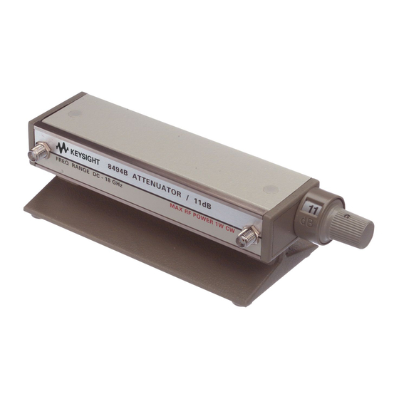
- Page 1 Keysight 8494/95/96A/B Attenuators Operating and Service Manual...
- Page 2 FAR 27.401 or DFAR could result in personal injury or death. 227.7103-5 (c), as applicable in any Do not proceed beyond a WARNING technical data. notice until the indicated conditions are fully understood and met. Keysight 8494/95/96A/B Operating and Service Manual...
-
Page 3: Environmental Conditions
Forty years electrical or electronic product in is the expected useful life of the product. domestic household waste. Keysight 8494/95/96A/B Operating and Service Manual... -
Page 4: Waste Electrical And Electronic Equipment (Weee) Directive 2002/96/ Ec
To contact Keysight for sales and technical support, refer to the support links on the following Keysight websites: – www.keysight.com/find/mta (product-specific information and support, software and documentation updates) – www.keysight.com/find/assist (worldwide contact information for repair and service) Keysight 8494/95/96A/B Operating and Service Manual... -
Page 5: Table Of Contents
.........27 Keysight 8494/95/96A/B Operating and Service Manual... - Page 6 ......... . . 27 Keysight 8494/95/96A/B Operating and Service Manual...
- Page 7 Dimensions of Keysight 8494/95/96A/B Attenuators Figure 4-1 Operator’s check setup ......25 Keysight 8494/95/96A/B Operating and Service Manual...
- Page 8 THIS PAGE HAS BEEN INTENTIONALLY LEFT BLANK. Keysight 8494/95/96A/B Operating and Service Manual...
- Page 9 .....24 Table 4-2 Attenuator and SWR settings ....26 Keysight 8494/95/96A/B Operating and Service Manual...
- Page 10 THIS PAGE HAS BEEN INTENTIONALLY LEFT BLANK. Keysight 8494/95/96A/B Operating and Service Manual...
- Page 11 Keysight 8494/95/96A/B Attenuators Operating and Service Manual Introduction Product Overview This chapter provides an overview of the Keysight 8494/95/96A/B Attenuators.
-
Page 12: Introduction Product Overview
10 μs. Do not connect an attenuator RF input or output connector to greater than ±7 Vdc. If the attenuator must be connected to a device with a potential greater than ±7 Vdc, use a blocking capacitor. Keysight 8494/95/96A/B Operating and Service Manual... -
Page 13: Instrument Options
Keysight 8494/95/96A/B Attenuators Operating and Service Manual Installation Initial Inspection Instrument Options Mating Connectors Installation Instructions This chapter provides you important information on how to check and prepare your instrument for operation. -
Page 14: Installation
“Sales and Technical Support” on page 4 of this manual for the Keysight Technologies nearest to you. Attach a tag indicating the type of service required, return address, model number, and serial number. Mark the container FRAGILE to insure careful handling. In any correspondence, refer to the instrument by model number and serial number. -
Page 15: Instrument Options
When installing the instrument, make sure that the connectors do not CAUTION support weight or bear torque. The preferred procedure is to set up all equipment in position before connecting the instrument. Either connector may be used as the input or output connector. Keysight 8494/95/96A/B Operating and Service Manual... -
Page 16: Installation Instructions
4-40 screws into the screw holes in the bottom of the attenuator. Removing the base and mounting the attenuator does not affect the performance of the attenuator. Keysight 8494/95/96A/B Operating and Service Manual... - Page 17 Keysight 8494/95/96A/B Attenuators Operating and Service Manual Specifications Specifications This chapter provides the specifications of the 8494/95/96A/B attenuators.
-
Page 18: Specifications
12.4 to selection (dB) 4 GHz 12.4 GHz 18 GHz 4 GHz 12.4 GHz 18 GHz 4 GHz 12.4 GHz 18 GHz — — — — — — — — — — — — Keysight 8494/95/96A/B Operating and Service Manual... -
Page 19: Maximum Swr
Specifications Maximum SWR Table 3-3 Maximum residual attenuation Attenuation repeatability ±0.03 dB max (5 million cycles per section). Keysight 8494/95/96A/B Operating and Service Manual... -
Page 20: Rf Power Handling Capability
[a] Dimensions are for general information only. If dimensions are required for building special enclosures, contact your Keysight field engineer. [b] Weight and width of the instrument vary with the option selected due to the type of connectors. Keysight 8494/95/96A/B Operating and Service Manual... - Page 21 [2] Keysight 8494A, B, 8495D, 8496A, B (0.49) Note: Base can be removed by user to access mounting Dimensions are in mm (inches) nominal, unless otherwise specified. holes as shown. Figure 3-1 Dimensions of Keysight 8494/95/96A/B Attenuators Keysight 8494/95/96A/B Operating and Service Manual...
- Page 22 Specifications THIS PAGE HAS BEEN INTENTIONALLY LEFT BLANK. Keysight 8494/95/96A/B Operating and Service Manual...
- Page 23 Keysight 8494/95/96A/B Attenuators Operating and Service Manual Operating Guide Operating Instructions Performance Tests Service Instructions This chapter provides simple quick-check instructions to verify the attenuators’ functionality prior to usage. It also provides information on service and maintenance of the attenuators.
-
Page 24: Operating Guide
Operating Guide Operating Instructions After the instrument is connected, the attenuation may be selected. Turn counterclockwise to increase attenuation or clockwise to decrease attenuation. Keysight 8494/95/96A/B Operating and Service Manual... -
Page 25: Operator's Check
The SWR meter used in this check is calibrated for a square-law detector. NOTE Therefore, the range changes and errors (read in dB) are twice that indicated by the meter. SWR meter Function generator Attenuator Adapter Adapter Input Output Ω Figure 4-1 Operator’s check setup Keysight 8494/95/96A/B Operating and Service Manual... -
Page 26: Attenuator And Swr Settings
— 0.30 0.75 — — 0.70 2.25 — 0.80 –0.30 — — 1.20 1.30 — 1.75 0.60 — — 1.75 2.40 [a] Adjust range by 2 dB, if needed, to obtain an on-scale indication. Keysight 8494/95/96A/B Operating and Service Manual... -
Page 27: Performance Tests
Operating Guide Performance Tests The Keysight 8494/95/96A/B Attenuators can be tested to the accuracy of the specifications with a network analyzer or equivalent equipment of suitable accuracy. If a network analyzer is available, test instrument using the procedure in the analyzer's operating manual. - Page 28 Operating Guide THIS PAGE HAS BEEN INTENTIONALLY LEFT BLANK. Keysight 8494/95/96A/B Operating and Service Manual...
- Page 29 This information is subject to change without notice. Always refer to the English version at the Keysight website for the latest revision. © Keysight Technologies 2011 - 2016 Edition 5, June 30, 2016 Printed in Malaysia *08494-90008* 08494-90008 www.keysight.com...
Need help?
Do you have a question about the 8494 and is the answer not in the manual?
Questions and answers