Keysight Technologies VXI bus 75000 C Series Service Manual
Command module
Hide thumbs
Also See for VXI bus 75000 C Series:
- Configuration and user's manual (88 pages) ,
- User manual (290 pages)
Table of Contents
Advertisement
Quick Links
Advertisement
Table of Contents

Related Manuals for Keysight Technologies VXI bus 75000 C Series


Summary of Contents for Keysight Technologies VXI bus 75000 C Series
- Page 1 75000 Series C Keysight E1406A Command Module Service Guide...
-
Page 3: Declaration Of Conformity
WITHOUT NOTICE, IN FUTURE EDI- without prior agreement and written con- www.keysight.com/find/E1406A TIONS. FURTHER, TO THE MAXIMUM sent from Keysight Technologies, Inc. as EXTENT PERMITTED BY APPLICABLE (product-specific information and sup- governed by United States and interna- LAW, KEYSIGHT DISCLAIMS ALL WAR- port, software and documentation tional copyright laws. -
Page 4: Safety Information
If necessary, return instrument chassis and cover must be safe operating conditions, modules the product to a Keysight Technologies connected to an electrical ground to should not be operated beyond the full Sales and Service Office for service and minimize shock hazard. - Page 5 Safety Symbols A CAUTION denotes a hazard. It calls attention to an operating pro- cedure or practice, that, if not cor- rectly performed or adhered to could result in damage to the product or loss of important data. Do not proceed beyond a CAUTION notice until the indicated condi- tions are fully understood and met.
-
Page 7: Table Of Contents
Contents 1 General Information Introduction ........... . 11 Safety Information . - Page 8 Typical Results..........36 Test F-2: General System Information.
- Page 9 Determine the Module Version....... . 87 Ship the Module to Keysight Technologies ..... . 88 5 Error Messages Introduction .
- Page 10 Keysight E1406A Command Module Service Guide...
-
Page 11: General Information
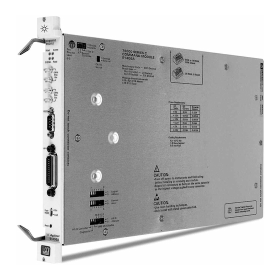
Keysight E1406A Command Module Service Guide General Information Introduction This service manual contains information to test, troubleshoot, and repair the Keysight E 1406A Command Module. Figure 1-1 shows a typical E1406A Command Module. See “Keysight 75000 Series C Service Documentation”, page 4, for a list of manuals that describe mainframe and command module operation and hardware. -
Page 12: Safety Information
General Information Safety Information Safety Information The Keysight E 1406A Command Module is a Safety Class I instrument that is provided with a protective earth terminal when installed in the mainframe. Check the mainframe, command module, and all related documentation for safety markings and instructions before operating or servicing a command module. -
Page 13: Cautions
Safety Information General Information REMOVE POWER IF POSSIBLE. Some procedures in this manual may be performed with power supplied to the mainframe while protective covers are removed. Energy available at many points may, if contacted, result in personal injury. (If service can be performed without power applied, remove the power.) USING AUTOTRANSFORMERS. -
Page 14: Product Information
See Appendix A - Specifications in the Keysight E 1406A Command Module User’s Manual for command module specifications. Serial Numbers Figure 1-2 shows Keysight Technologies serial number structure. Keysight E 1406A Command Modules covered by this manual are identified by the serial number prefixes listed on the title page. -
Page 15: Options
Table 1-2 shows available upgrade paths for the Keysight E 1406A Command Module and the upgrade kit(s) required. You can order the upgrade kits from your nearest Keysight Technologies Sales and Support Office. (A list of these offices is at the back of this manual.) -
Page 16: Recommended Test Equipment
General Information Inspection/ Shipping Recommended Test Equipment See Table 1-4 for test equipment recommended to test and service the command module. Essential requirements for each piece of test equipment are listed in the Requirements column. You may substitute other equipment if it meets the requirements in Table 1-4. - Page 17 Inspection/ Shipping General Information Figure 1-3 Initial (Incoming) Inspection Guidelines Keysight E1406A Command Module Service Guide...
-
Page 18: Shipping Guidelines
Technologies Sales and Support Office or to a Service Center. Figure 1-4 Packaging/Shipping Guidelines * We recommend you use the same shipping materials as those used in factory packaging (available from Keysight Technologies). For other (commercially-available) shipping materials, use a double-wall carton with minimum 2.4 MPa (350 psi) test. -
Page 19: Verification Tests
Keysight E1406A Command Module Service Guide Verification Tests Introduction This chapter describes Keysight E1406A Command Module self-tests and functional verification tests. There are no operation verification tests, performance verification tests, or user adjustments for the command module. Table 2-1 defines command module self-tests and functional verification tests and suggests when to use each type of test. -
Page 20: Command Module Configuration
Verification Tests Command Module Configuration Command Module Configuration This section shows how to set an Keysight E1406A Command Module for factory settings, and summarizes basic command module functions. See the C-Size VXIbus Systems Configuration Guide for information on changing command module switch settings. - Page 21 Command Module Configuration Verification Tests Figure 2-1 Command Module Switches - Factory Settings Be sure switches are COMPLETELY seated in the proper position. Switches may appear to be in the correct position but may not be fully seated. One way to ensure that switches are seated is to listen for a “click”...
-
Page 22: Some Command Module Definitions
Verification Tests Command Module Configuration Some Command Module Definitions In this manual, the VXIbus “system” assumed is an external controller connected to a command module via GPIB, with the command module configured as the resource manager and the slot 0 device. The following paragraphs summarize some terms associated with the command module. -
Page 23: Commander/Servant Areas
Command Module Configuration Verification Tests – Primary GPIB address (set with the GPIB Address switch) – Secondary GPIB address (derived from the Logical Address) Instruments are located by the GPIB address. For example, Figure 2-2 shows a typical GPIB Address. The GPIB Primary Address is set with the GPIB Address switch (switch 6 in Figure 2-1). - Page 24 Verification Tests Command Module Configuration Figure 2-3 Example: Command/Servant Hierarchy Keysight E1406A Command Module Service Guide...
-
Page 25: Command Module Self-Tests
Command Module Self-Tests Verification Tests Command Module Self-Tests This section shows how to perform Keysight E1406A Command Module self-tests using the GPIB power-on test and/or RS-232 power-on test. Either test is usually adequate to verify that a command module is operational. If a self-test fails, see Chapter 4 - Service for further tests/information. -
Page 26: Example Program
Verification Tests Command Module Self-Tests Figure 2-4 Test S-1: GPIB Power-On Test Example Program This program performs an GPIB power-on test for the Keysight E1406A command module and uses the SYST:ERR? command to check results. If the power-on test passes, +0,"No error" is returned. If the power-on test fails, the test returns an error message for each error detected. -
Page 27: Typical Result
Command Module Self-Tests Verification Tests 30DIM Err_msg$[256] 40PRINT “Test S-1: GPIB Power-On Self-Test” 50PRINT 60PRINT “This test checks for power-on errors in the command module.” 70PRINT “To perform this test:” 80PRINT 90PRINT “ 1. Turn mainframe power OFF” 100 PRINT “ 2. -
Page 28: Test S-2: Rs-232 Power-On Self-Test
Verification Tests Command Module Self-Tests Test S-2: RS-232 Power-On Self-Test Description This test checks the command module power-on and configuration sequence. The test requires an RS-232 terminal (such as an HP 700/94 or equivalent) connected to the RS-232 terminal of the command module. The command module power-on sequence can be monitored on an RS-232 terminal (or printer) that is connected to the command module’s RS-232 port. - Page 29 Command Module Self-Tests Verification Tests Keysight E1406A Command Module Typical Resource Manager Configuration Sequence Testing ROM Testing512K Bytes RAM Passed CPU Self Test Passed GPIB address: 09 Talk/Listen Command Module ladd = 0 Command Module servant area = 255 Command Module VME bus timeout = ENABLED Searching for static devices in mainframe 0 SC Device at ladd 0 in slot 0 Searching for dynamic devices...
- Page 30 Verification Tests Command Module Self-Tests SYSTEM INSTALLED AT SECONDARY ADDR 0 VOLTMTR INSTALLED AT SECONDARY ADDR 1 SWITCH INSTALLED AT SECONDARY ADDR 2 MBinstr INSTALLED AT SECONDARY ADDR 3 SYSTEM instrument started BNO issued to ladd 24, BNO response = FFFE Opening GPIB access for message based device at sec addr 03 1 The Keysight E1406A operating system performs a series of self-tests and clears its volatile RAM.
-
Page 31: Functional Verification Tests
Functional Verification Tests Verification Tests Functional Verification Tests This section describes functional verification tests for the Keysight E1406A Command Module. These (optional) tests can be used to check specific command module functions. Typically, functional verification tests are used after repair or whenever command module operation is questionable. Table 2-3 lists functional verification tests for the command modules. -
Page 32: Test F-1: Front Panel Outputs
Verification Tests Test F-1: Front Panel Outputs Test F-1: Front Panel Outputs Description This test checks the output levels from the front panel Trig Out and Clk Out ports. There are four parts to the test, as follows. See Figure 2-6 for a summary of the trigger sources and paths for parts A, B, and C. -
Page 33: Set Up Equipment
Test F-1: Front Panel Outputs Verification Tests Set up Equipment – Turn mainframe power OFF – Connect oscilloscope to command module (see Figure 2-7) – Set up oscilloscope (see Figure 2-7) – Turn mainframe power ON Figure 2-7 Test F-1: Front Panel Outputs Connections Keysight E1406A Command Module Service Guide... -
Page 34: Example Program
Verification Tests Test F-1: Front Panel Outputs Example Program This program runs the three Trig Out tests and the Clk Out test described above. 1!Test F-1: Front Panel Outputs 10ASSIGN @Addr to 70900!Assign @Addr to cmd module 20PRINT “Part A: INTernal Trigger Source Test” 30PRINT 40PRINT “Connect oscilloscope to command module Trig Out port”... - Page 35 Test F-1: Front Panel Outputs Verification Tests 280OUTPUT @Addr;"OUTP:EXT:SOUR “;Trg_sour$(I)!Allows Trig Out port to be driven by selected TTLTrg/ECLTrg trigger line 290OUTPUT @Addr;"OUTP:"&Trg_sour$(I)&":LEV ON"!Set selected trigger line to ON 300WAIT 2!Wait 2 seconds 310OUTPUT @Addr;"OUTP:"&Trg_sour$(I)&":LEV OFF"!Set selected trigger line to OFF 320DISP “...
-
Page 36: Typical Results
Verification Tests Test F-1: Front Panel Outputs PRINT “Part D: 10 MHz Clk Out Signal Test” PRINT PRINT “Connect oscilloscope to command module Clk Out port” DISP “ Press Continue when ready to run this test ” PAUSE CLEAR SCREEN Typical Results See Figure 2-6 for oscilloscope displays for Trig Out port tests (Parts A, B, and C). -
Page 37: Test F-2: General System Information
Test F-2: General System Information Verification Tests Test F-2: General System Information Description This test uses the following commands to return information on command module addresses, number of devices in the system, and system version, time, and date settings. SYST:COMM:GPIB:ADDR? Command module GPIB address VXI:CONF:DNUM? Number of devices in the system... -
Page 38: Typical Results
Verification Tests Test F-2: General System Information 1!Test F-2: General System Information 10ASSIGN @Addr to 70900!Assign @Addr to cmd module 20DIM Ladds$[256]!Dimension Logical Address storage 30OUTPUT @Addr;"SYST:COMM:GPIB:ADDR?"!Query GPIB address 40ENTER @Addr;Cmd_addr 50OUTPUT @Addr;"VXI:CONF:DNUM?"!Query number of modules installed 60ENTER @Addr;Dnum 70OUTPUT @Addr;"VXI:CONF:LADD?"!Query device Logical Addresses 80ENTER @Addr;Ladds$ 90OUTPUT @Addr;"SYST:VERS?"!Query version for SCPI compliance 100ENTER @Addr;Vers$... -
Page 39: Test F-3: Hierarchy/Device Information
Test F-3: Hierarchy/Device Information Verification Tests Test F-3: Hierarchy/Device Information Description This test uses VXI:CONF:HIER? and VXI:CONF:INF? to return current hierarchy configuration and static information for the module at the logical address you select. The information returned by each command follows. See the Keysight E1406A Command Module User’s Manual for details on each entry. -
Page 40: Set Up Equipment
Verification Tests Test F-3: Hierarchy/Device Information Device Class Integer between 0 and 5 0 = VXIbus memory device 1 = VXIbus extended device 2 = VXIbus message based device 3 = VXIbus register based device 4 = hybrid device 5 = Non-VXIbus device Address Space Integer from 0 to 15 (Integer value is sum of 1 = device has A16 registers... -
Page 41: Example Program
Test F-3: Hierarchy/Device Information Verification Tests Figure 2-10 Test F-3: Hierarchy Info Connections Example Program This program uses VXI:CONF:HIER? and VXI:CONF:INF? to return current hierarchy configuration and static information for the module at the logical address you select. 1!Test F-3: Hierarchy/Device Information 3!—————————————- Query system Logical Addresses ————————... - Page 42 Verification Tests Test F-3: Hierarchy/Device Information 30DIM Rinf$(16)[50],Hinf$(18)[50], Hier$[1000],Inf$[1000] !Dimension storage variables 40OUTPUT @Addr;"*RST"!Reset cmd module 50OUTPUT @Addr;"VXI:CONF:LADD?"!Query system Logical Addresses 60ENTER @Addr;Laddr$ 70PRINT TABXY(1,18),"System Logical Addresses are: “;Laddr$ 80INPUT “ Enter Logical Address of module to check. Then, press Continue.
- Page 43 Test F-3: Hierarchy/Device Information Verification Tests 380 PRINT “ - Pass/Failed: ”;Hinf$(17) 390PRINT “ - Manufacturer’s Comments: ”;Hier$[Scn1] 400DISP “ Record results as desired. Then, press Continue for VXI:CONF:INF? results. ” 410PAUSE 420CLEAR SCREEN 421! ———————-Use VXI:CONF:INF? Command ————— 430OUTPUT @Addr;"VXI:CONF:INF?"!Query module at sel Logical Address 440ENTER 70900;Inf$ 450INTEGER Scn,Fnd...
-
Page 44: Typical Results
Verification Tests Test F-3: Hierarchy/Device Information Typical Results The following tables show typical results for a command module at Logical Address 0, with the command module being the only module installed in the mainframe. If the information about the selected logical address is not available (i.e., the requested device is not in the mainframe or in the command module’s servant area), Error -224 (“parameter error”) is set and no data is returned. -
Page 45: Vxi:conf:inf? Command Results
Test F-3: Hierarchy/Device Information Verification Tests VXI:CONF:INF? Command Results - Logical Address: - Manufacturer ID: +4095 (Keysight Technologies is manufacturer) - Model Code: (20 =E1406 Command Module Code) - Device Class: (VXIbus message based device) - Address Space: (device has A16 and A24... -
Page 46: Test F-4: Table/Memory Information
Verification Tests Test F-4: Table/Memory Information Test F-4: Table/Memory Information Description This test uses the following commands to return information on command module Configuration Table addresses and memory addresses/sizes. See Chapter 2 in the Keysight E1406A Command Module User’s Manual for Configuration Table definitions. -
Page 47: Example Program
Test F-4: Table/Memory Information Verification Tests Figure 2-11 Test F-4: Table/Memory Info Connections Example Program This program uses the commands listed in the Description section to return information on Command Module Configuration Table addresses and memory addresses/sizes. 1!Test F-4: Table/Memory Information 3! ————————- Get Configuration Table Information ————————————- 10 ASSIGN @Addr to 70900 !Assign @Addr to cmd module 20 DIM Dvr_list$[1000]... - Page 48 Verification Tests Test F-4: Table/Memory Information 80 ENTER @Addr;Etab$ 90 OUTPUT @Addr;"VXI:CONF:ITAB?" !Interrupt Line Allocation Table address 100 ENTER @Addr;Itab$ 101 ! — —— — —— —— —- Get Comman d Module Memory Information —— — —— —— — —— - 110 OUTPUT @Addr;"VXI:CONF:MTAB?"...
- Page 49 Test F-4: Table/Memory Information Verification Tests 440PRINT “ - Current NRAM size (bytes):”;Nram_cre$ 450PRINT “ - Maximum NRAM size (bytes):”;Nram_max$ 460PRINT “ - RDISK starting address:”;Rdis_addr$ 470PRINT “ - Current RDISK size (bytes):”;Rdis_cre$ 480PRINT “ - Maximum RDISK size (bytes):”;Rdis_max$ 490PRINT “...
- Page 50 Verification Tests Test F-4: Table/Memory Information 770 PAUSE 780 WAIT 5 790 OUTPUT @Addr;"DIAG:FROM:AVA?"! Flash ROM Available 800 ENTER @Addr; Fava$ 810 OUTPUT @Addr;"DIAG:FROM:SIZE?"! Flash ROM Size 820 ENTER @Addr;Fsize$ 830 OUTPUT @Addr;"DIAG:FROM:CRE?"! Flash ROM Created 840 ENTER @Addr;Fcre$ 850 PRINT “Flash ROM Space set to 0.” 860 PRINT 870 PRINT “Flash ROM Available: ”;Fava$ 880 PRINT “Flash ROM Size: ”;Fsize$...
-
Page 51: Typical Results
Test F-4: Table/Memory Information Verification Tests 1120 PRINT “Flash ROM set to maximum” 1130 PRINT 1140 PRINT “Flash Rom Available: ”;Fava$ 1150 PRINT “Flash Rom Size: ”;Fsize$ 1160 PRINT “Flash Rom Created for Drivers: ”;Fcre$ 1170 END Typical Results Typical results follow for a command module ONLY installed in the mainframe (this does not show the step instructions). - Page 52 Verification Tests Test F-4: Table/Memory Information Flash ROM Created for Drivers: +0 Flash ROM set to maximum Flash ROM Available: +1048576 Flash ROM Size: +1048576 Flash ROM Created for Drivers: +64 Keysight E1406A Command Module Service Guide...
-
Page 53: Test F-5: Interrupt/Status Information
Test F-5: Interrupt/Status Information Verification Tests Test F-5: Interrupt/Status Information Description This test uses the following commands to return information on command module interrupt lines and on register status. See Chapter 4 - Status and Interrupts in the Keysight E1406A Command Module User’s Manual for interrupt and status information. -
Page 54: Example Program
Verification Tests Test F-5: Interrupt/Status Information Figure 2-12 Test F-5: Interrupt/Status Info Connection Example Program This program uses the commands listed in Description to return information on command module interrupt lines and register status. 1!Test F-5: Interrupt/Status Information 3! ——————————————— Get Interrupt Information —————————- 10ASSIGN @Addr to 70900!Assign @Addr to cmd mod 20DIM Int_set$(7)[3] 30FOR I=1 TO 7!Loop to find states of interrupt lines 1-7... -
Page 55: Typical Results
Test F-5: Interrupt/Status Information Verification Tests 70OUTPUT @Addr;"STAT:OPER:COND?"!Query state of Condition Register 80ENTER @Addr;Oper_cond$ 90OUTPUT @Addr;"STAT:OPER:ENAB?"!Query Standard Operation Enable register mask value 100ENTER @Addr;Oper_enab$ 110OUTPUT @Addr;"STAT:OPER:EVEN?"!Query value of bit set in Event register 120ENTER @Addr;Oper_even$ 130OUTPUT @Addr;"STAT:QUES:ENAB?"!Query Questionable Status Register enable mask value 140ENTER @Addr;Ques_enab$ 141!—————————————- Display Results ——————————————... - Page 56 Verification Tests Test F-5: Interrupt/Status Information - State of interrupt line 1: - State of interrupt line 2: - State of interrupt line 3: - State of interrupt line 4: - State of interrupt line 5: - State of interrupt line 6: - State of interrupt line 7: OFF Status Information - State of Condition register:...
-
Page 57: Test F-6: Triggering Information
Test F-6: Triggering Information Verification Tests Test F-6: Triggering Information Description This test uses the following commands to return information on the ECLTrg and TTLTrg trigger lines, and on the Trig Out port. ECLTrg Trigger Lines (n = 0 or 1) OUTP:ECLT[n]:LEV? ECLTrg Line n Logic Level OUTP:ECLT[n]:SOUR? -
Page 58: Example Program
Verification Tests Test F-6: Triggering Information Figure 2-13 Test F-6: Triggering Info Connections Example Program This program uses the commands listed in the Description section to return information on the ECLTrg and TTLTrg trigger lines, and on the Command Module Trig Out port. 1! Test F-6: Triggering Information 10Assign @Addr to 70900!Assign @Addr to Cmd Mod 20DIM Elev$(2)[5],Esour$(2)[5],Estat$(2)[5]... - Page 59 Test F-6: Triggering Information Verification Tests 50OUTPUT @Addr;"OUTP:ECLT"&VAL$(I)&":LEV?"!Query ECLTrg Line 0 - 1 logic level 60ENTER @Addr;Elev$(I) 70OUTPUT @Addr;"OUTP:ECLT"&VAL$(I)&":SOUR?"!Query ECLTrg Line 0 - 1 source 80ENTER @Addr;Esour$(I) 90OUTPUT @Addr;"OUTP:ECLT"&VAL$(I)&":STAT?"!Query ECLTrg Line 0 - 1 state 100ENTER @Addr;Estat$(I) 110NEXT I 111! ——————————————- Get ECLTrg Line Information ———————————— 120FOR I=0 TO 7 130OUTPUT @Addr;"OUTP:TTLT"&VAL$(I)&":LEV?"!Query TTLTrg lines 0 - 7 logic level...
-
Page 60: Typical Results
Verification Tests Test F-6: Triggering Information 370 PRINT “ - Trig Out Port:”;Slev$,Ssour$,Sstat$ 380 END Typical Results Typical results follow for a Command Module with all TTLTrg and ECLtrg Lines and the Trig Out port set at level 0, no source, and state 0. Test F-6: Triggering Information Level Source... -
Page 61: Test F-7: Serial Port Information
Test F-7: Serial Port Information Verification Tests Test F-7: Serial Port Information This test uses the following commands to return information on the command module serial (RS-232) port. DIAG:COMM:SER:OWN? Serial port ownership SYST:COMM:SER:BAUD? Baud rate SYST:COMM:SER:CONT:DTR? DTR mode line SYST:COMM:SER:CONT:RTS? RTS mode line SYST:COMM:SER:BITS? Bits setting SYST:COMM:SER:SBIT? Number of stop bits SYST:COMM:SER:PACE:THR:STAR? STARt threshold level... -
Page 62: Example Program
Verification Tests Test F-7: Serial Port Information Figure 2-14 Test F-7: Serial Port Info Connections Example Program This program uses the commands listed in the Description section to return information on the current Command Module Serial (RS-232) Port settings. 1!Test F-7: Serial Port Information 10Assign @Addr to 70900!Assign @Addr to cmd module 20OUTPUT @Addr;"DIAG:COMM:SER:OWN?"!Query serial port ownership 30ENTER @Addr;Own$... - Page 63 Test F-7: Serial Port Information Verification Tests 90ENTER @Addr;Rts$ 100OUTPUT @Addr;"SYST:COMM:SER:BITS?"!Query bits setting 110ENTER @Addr;Bits 120OUTPUT @Addr;"SYST:COMM:SER:SBIT?"!Query number of stop bits 130ENTER @Addr;Sbits 140OUTPUT @Addr;"SYST:COMM:SER:PACE:THR:STAR?" !Query STARt threshold level 150ENTER @Addr;Star 160OUTPUT @Addr;"SYST:COMM:SER:PACE:THR:STOP?" !Query STOP threshold level 170ENTER @Addr;Stop 180OUTPUT @Addr;"SYST:COMM:SER:PAR:CHEC?"!Query receive parity check state 190ENTER @Addr;Chec 200OUTPUT @Addr;"SYST:COMM:SER:PAR?"!Query current parity type...
-
Page 64: Typical Results
Verification Tests Test F-7: Serial Port Information 430 PRINT “ - Transmit/receive pacing linkage: ”;Auto$ 440 PRINT “ - Receive pacing protocol state: ”;Rpace$ 450 PRINT “ - Transmit pacing protocol state: ”;Space$ 460 END Typical Results Typical results follow for a command module RS-232 serial port. Test F-7: Serial Port Information - Serial port ownership: SYST... -
Page 65: Replaceable Parts
This chapter contains information to order replaceable parts or exchange modules for the Keysight E 1406A Command Module. To order a part or exchange assembly listed in this chapter, specify the Keysight Technologies part number and the quantity required. Send the order to your nearest Keysight Technologies Sales and Support Office. - Page 66 Replaceable Parts Replaceable Parts Lists Table 3-2 E1406A Command Module Replaceable Parts Reference* Keysight Part Description Mfr* * Mfr Part Designator Code Number Number REPLACEMENT MODULES E1406-66201 REPLACEMENT CONTROLLER MODULE (STANDARD) E1406-66202 REPLACEMENT CONTROLLER MODULE (EXP. MEMORY) Keysight E1406A HARDWARE PARTS (Fig. 3-1) E1300-86401 BATTERY PACK, 3.6V W/2 28480...
- Page 67 DE US 19801 26742 METHODE ELECTRONICS INC CHICAGO 60656 27264 MOLEX INC LISLE 60532 Keysight TECHNOLOGIES INC - CORPORATE 28480 PALO ALTO CA US 94304 INSTRUMENT SPECIALTIES CO INC 30817 DEL WATER GAP PA US 18327 THOMAS & BETTS CORP...
-
Page 68: Component Locators
Replaceable Parts Component Locators Component Locators Figures 3-1 and 3-2 show locations of selected replaceable parts for the Keysight E 1406A Command Module. Figure 3-1 Keysight E1406A Replaceable Parts Keysight Keysight E1406A Command Module Service Guide... - Page 69 Component Locators Replaceable Parts Figure 3-2 Keysight E1406A A1 PCA Replaceable Parts Keysight Keysight E1406A Command Module Service Guide...
- Page 70 Replaceable Parts Component Locators Keysight Keysight E1406A Command Module Service Guide...
-
Page 71: Service
– troubleshooting guidelines – assembly/disassembly instructions – repair/maintenance guidelines – returning module to Keysight Technologies Do not perform any of the service procedures shown unless you are a qualified, service-trained person, and have read the WARNINGS and CAUTIONS in Chapter 1. -
Page 72: Troubleshooting
Service Troubleshooting Troubleshooting This section shows suggested steps to troubleshoot Keysight E1406A Command Module faults to a fuse on the A1 PCA or to a replaceable mechanical part listed in Table 3-2. See Figure 4-1 for suggested steps. 1 Prepare the Mainframe To begin troubleshooting, turn the mainframe power switch OFF and remove all power sources to any installed modules. - Page 73 Troubleshooting Service Figure 4-1 E1406A Command Module Troubleshooting Keysight E1406A Command Module Service Guide...
-
Page 74: Ready Led (Only) On
Service Troubleshooting 3 Ready LED (ONLY) ON When the “Ready” LED is ON, normal operation is indicated. However, there may be configuration errors. If you have an RS-232 terminal connected, check the terminal display for configuration errors (see Chapter 5 - Error Messages for code explanations). -
Page 75: Check Command Module
Troubleshooting Service 6 Check Command Module If the “Failed” and/or “SYSFAIL” LEDs remain ON after 5 seconds, turn mainframe power OFF and remove the command module from the mainframe. – Check the command module switch settings for correct settings. See Figure 2-1 for switch locations. -
Page 76: Assembly/ Disassembly Instructions
Service Assembly/ Disassembly Instructions – If the command module is repairable (see “Repair Strategy” for guidelines), repair and reinstall the module. Then, turn mainframe power ON and rerun Step 2 - Check LEDs and Terminal Display. – If the module is not repairable, replace the entire module. Install a new command module, turn mainframe power ON and rerun Step 2 - Check LEDs and Terminal Display. - Page 77 Assembly/ Disassembly Instructions Service Keysight E1406A Command Module Service Guide...
- Page 78 Service Assembly/ Disassembly Instructions Keysight E1406A Command Module Service Guide...
- Page 79 Assembly/ Disassembly Instructions Service Keysight E1406A Command Module Service Guide...
- Page 80 Service Assembly/ Disassembly Instructions Be sure switches are COMPLETELY seated in the proper position. Switches in the correct position but may not be fully seated. may appear to be One way to ensure that switches are seated is to listen for a “click” as you depress the switch.
- Page 81 Assembly/ Disassembly Instructions Service Keysight E1406A Command Module Service Guide...
- Page 82 Service Assembly/ Disassembly Instructions Keysight E1406A Command Module Service Guide...
- Page 83 Assembly/ Disassembly Instructions Service Keysight E1406A Command Module Service Guide...
- Page 84 Service Assembly/ Disassembly Instructions Keysight E1406A Command Module Service Guide...
-
Page 85: Repair/ Maintenance Guidelines
Repair/ Maintenance Guidelines Service Repair/ Maintenance Guidelines Guidelines to repair and maintain an Keysight E1406A Command Module follow, including: – ESD precautions – Soldering printed circuit boards – Post-repair safety checks Do not touch the command module edge connector pins at any time unless you are actively using a static-free workstation. -
Page 86: Post-Repair Safety Checks
Service Repair/ Maintenance Guidelines – Avoid unnecessary component unsoldering and soldering. Excessive replacement can result in damage to the circuit board and/or adjacent components. – Do not use a high power (>30 watts) soldering iron on etched circuit boards, as excessive heat may lift a conductor or damage the board. –... -
Page 87: Returning An Keysight E1406A
Service Returning an Keysight E1406A Use the following procedures to return an Keysight E1406A Command Module to Keysight Technologies. Determine the Module Version [a] If the model label is attached to the bottom shield of the command module (see Figure 4-3 for location), note the model number on the upper label of the bottom shield of the module. -
Page 88: Ship The Module To Keysight Technologies
Service Returning an Keysight E1406A Ship the Module to Keysight Technologies Package the module and ship it to Keysight Technologies. See Chapter 1 - General Information for packaging details. Keysight E1406A Command Module Service Guide... -
Page 89: Error Messages
Keysight E1406A Command Module Service Guide Error Messages Introduction This chapter shows how to read the Keysight E 1406A Command Modules error queue, and provides error message listings and probable causes. Error Message Types Table 5-1 shows the four categories of error messages for the Keysight E 1406A Command Modules. -
Page 90: Configuration Errors
Hardware Errors: Indicates m ajor hardware failure of com m and m odule. Usually requires returning the m odule to Keysight Technologies for service. Read errors from a term inal connected to the RS-232 port of the com m and m odule. - Page 91 Introduction Error Messages E rror codes read from the error queue are preceded by the num ber 21. For exam ple, error code 11 displayed on an R S-232 term inal or printer appears as 2111 when returned by the SYST :ERR? com m and.
- Page 92 Error Messages Introduction Table 5-2 Language Related Errors (continued) - 253 CORRUPT MEDIA An incorrect checksum was read from the program m ed ROMs. This is indicative of a ROM hardware m alfunction or a data transm ission error. - 258 MEDIA PROTECTED A com m and was executed with the “...
- Page 93 Introduction Error Messages Table 5-3 Command Module Resource Manager Configuration Errors (continued) A32 MEMORY OVERFLOW There is not enough available A32 memory required for a device. The allowable memory space is from 20000000h to FFFFFFFFh (E0000000h - FFFFFFFFh is only used if there is a 2000 Mbyte device in the system). If your system has (mainframe) extenders, try using the user-defined extender table to allocate the memory more efficiently.
- Page 94 Error Messages Introduction Table 5-3 Command Module Resource Manager Configuration Errors (continued) BNO was issued to a message-based device whose response BNO FAILED indicated an error condition. The Begin Normal Operation command may have failed or the device returned a response other than FFFEh.
- Page 95 Introduction Error Messages Table 5-3 Command Module Resource Manager Configuration Errors (continued) The diagnostic switch on the command module is set to ’1’. Only DIAGNOSTIC MODE ON the system instrument is started. No other modules receive WARNING BNO. RESOURCE MANAGER NOT The command module is the resource manager (logical address = IN SLOT 0 WARNING...
- Page 96 Error Messages Introduction Table 5-3 Command Module Resource Manager Configuration Errors (continued) The valid flag in the user-defined interrupt line allocation table is INVALID UDEF INTR TABLE not true (1). VXI:CONF:ITAB < address> has been set but is pointing to an invalid table. Either the table is corrupt or has not been downloaded.
- Page 97 Introduction Error Messages Table 5-3 Command Module Resource Manager Configuration Errors (continued) DEVICE OUTSIDE OF LADD A module in an (extender) mainframe is outside of the logical address WINDOW window set by the resource manager or set by the user-defined extender table. Either reset the logical addresses or download a new extender table.
- Page 98 Error Messages Introduction Table 5-3 Command Module Resource Manager Configuration Errors (continued) INTX daughter card is not installed on the VXI-MXI extender INTX CARD NOT INSTALLED module. The resource manager expects the INTX card to be installed in order for * SYSRESET and interrupts to propagate throughout the system.
- Page 99 Introduction Error Messages Table 5-4 System Instrument Errors (continued) CONFIG. ERROR 8 A 24 memory device overlaps memory space reserved by the 2108 mainframe’s operating system. CONFIG. ERROR 10, Too many instruments installed in the mainframe. Cannot 2110 INSUFFICIENT SYSTEM configure instruments.
- Page 100 Error Messages Introduction Table 5-4 System Instrument Errors (continued) Insufficient system resources to allow the IBASIC file system to 2131 FILE SYSTEM STARTUP FAILED start. 2133 INVALID UDEF MEMORY BLOCK Invalid memory block in user define memory table. 2134 UDEF MEMORY BLOCK The same base address or memory are specified more than once in the UNAVAILABLE Memory table, or the addresses in the specified block are...
- Page 101 Introduction Error Messages Table 5-4 System Instrument Errors (continued) 2153 INVALID EXTENDER A24 MXIbus extender cannot be configured with a valid A32 memory window. WINDOW An A24 memory device is located outside the allowable logical 2154 DEVICE OUTSIDE OF A24 address window range of a MXIbus extender.
- Page 102 Error Messages Introduction Table 5-5 Operating System Errors Type Message Cause System Errors SYSTEM ERROR: Out of PCB Extensions SYSTEM ERROR in os_fork_ui Usually caused by adding non-Keysight cards. To correct, remove non-Keysight register-based cards and re-boot. Error Status: If the error reoccurs, replace ROMs. SYSTEM ERROR in os_fork_twin Error Status: SYSTEM ERROR in os_fork_display...
- Page 103 Introduction Error Messages Table 5-5 Operating System Errors (continued) Hardware Errors SYSTEM ERROR: Uninitialized CHECK Trap SYSTEM ERROR: Uninitialized TRAPV Trap SYSTEM ERROR: Privileged Instruction SYSTEM ERROR: Uninitialized TRACE Trap SYSTEM ERROR: Uninitialized L1010 Trap SYSTEM ERROR: Uninitialized L1111 Trap SYSTEM ERROR: Format Error Trap SYSTEM ERROR: Uninitialized Vector 15 SYSTEM ERROR: Uninitialized TRAP4 SYSTEM ERROR: Uninitialized TRAP5...
- Page 104 Error Messages Introduction Table 5-5 Operating System Errors (continued) Self-Test Error Self Test: Error Messages Self Test: Gate Array Error For “Gate Array Error”, replace gate array. For “Bad ROM Checksum”, replace ROM. For “RAM Error”, replace RAM Bad ROM Checksum Self Test: RAM Error at Address: in Bus Error Register in Interrupt Mode Register in Interrupt Mask...
- Page 105 Introduction Error Messages Table 5-5 Operating System Errors (continued) Interrupt Error Address: PC: These are message-based card errors Messages SYSTEM ERROR: VXI “Command In” Interrupt (word-serial). For a “Command In” interrupt, message-based card sent a command that cannot be processed. SYSTEM ERROR: VXI “Signal In”...
- Page 106 Error Messages Introduction KeysightE1406A Command Module Service Guide...
-
Page 107: A Verification Tests - C Programs
Keysight E1406A Command Module Service Guide Verification Tests - C Programs Introduction This example program is a menu driven version of all the programs found in Chapter 2 - Verification Tests. The program source code is provided on the disk included with this manual. - Page 108 Verification Tests - C Programs Introduction ViStatus err; ViSession defaultRM, cm; viOpenDefaultRM (&defaultRM); viOpen (defaultRM, CM_ADDRESS, VI_NULL, VI_NULL, &cm); /* ----Set command module timeout----* / viSetAttribute(cm, VI_ATTR_TMO_VALUE, 15000); /* ----MENU for selection of tests----* / printf ("\n\n******** Keysight E1406A Functional Verification Test Menu ********\n\n");...
- Page 109 Introduction Verification Tests - C Programs while ((int)test_select > 8 | | (int)test_select < 0); switch ((int)test_select) case 0:power_on_test(cm,err); break; case 1:front_panel_outputs(cm,err); break; case 2:general_system_information(cm,err); break; case 3:hierarchy_device_information(cm,err); break; case 4:table_memory_information(cm,err); break; case 5:interrupt_status_information(cm,err); break; case 6:triggering_information(cm,err); break; case 7:serial_port_information(cm,err); break;...
- Page 110 Verification Tests - C Programs Introduction printf (" 1. Turn mainframe power OFF\n"); printf (" 2. Remove all modules (except command module) from mainframe\n"); printf (" 3. Turn mainframe power ON\n"); printf (" 4. Wait at least 5 seconds before running the test\n"); printf ("...
- Page 111 Introduction Verification Tests - C Programs fflush(stdin); printf ("\n Level should have dropped from + 5V to 0V\n"); printf (" Press ENTER to continue\n"); getchar (); err= viPrintf(cm, "OUTP:EXT:LEV OFF\n"); if(err< VI_SUCCESS) err_handler(cm,err); printf ("\nPart B: TTL/ECL Trigger Line Source Test\n"); printf ("\n Connect oscilloscope to command module Trig Out port\ n");...
- Page 112 Verification Tests - C Programs Introduction err= viPrintf(cm, "OUTP:ECLT%u:SOUR INT\n", i); if(err< VI_SUCCESS) err_handler(cm,err); err= viPrintf(cm, "OUTP:EXT:STAT ON\n"); if(err< VI_SUCCESS) err_handler(cm,err); err= viPrintf(cm, "OUTP:EXT:SOUR ECLT%u\n", i); if(err< VI_SUCCESS) err_handler(cm,err); err= viPrintf(cm, "OUTP:ECLT%u:LEV ON\n", i); if(err< VI_SUCCESS) err_handler(cm,err); printf ("\n Level should have dropped from + 5V to 0V\n"); printf ("...
- Page 113 Introduction Verification Tests - C Programs printf ("Trigger line being tested is: ECLT%u\n", i); err= viPrintf(cm, "OUTP:ECLT%u:STAT ON\n", i); if(err< VI_SUCCESS) err_handler(cm,err); err= viPrintf(cm, "OUTP:ECLT%u:SOUR EXT\n", i); if(err< VI_SUCCESS) err_handler(cm,err); err= viPrintf(cm, "OUTP:EXT:STAT ON\n"); if(err< VI_SUCCESS) err_handler(cm,err); err= viPrintf(cm, "OUTP:EXT:SOUR ECLT%u\n", i); if(err<...
- Page 114 Verification Tests - C Programs Introduction err= viPrintf(cm, "VXI:CONF:DNUM?\n"); /* Query number of modules installed* / if(err< VI_SUCCESS) err_handler(cm,err); err= viScanf(cm, "%t", result); if(err< VI_SUCCESS) err_handler(cm,err); printf (" -Number of devices in the system %s", result); err= viPrintf(cm, "VXI:CONF:LADD?\n"); /* Query device logical addresses * / if(err<...
- Page 115 Introduction Verification Tests - C Programs printf ("\n*** Hierarchy/Device Information ***\n"); err= viPrintf(cm, "* RST\n"); if(err< VI_SUCCESS) err_handler(cm,err); err= viPrintf(cm, "VXI:CONF:LADD?\n"); if(err< VI_SUCCESS) err_handler(cm,err); err= viScanf(cm,"%t",ladd); if(err< VI_SUCCESS) err_handler(cm,err); printf ("\n System Logical Addresses are: %s", ladd); printf ("\n Enter the Logical Address of the module to check:"); scanf ("%u", &laddr);...
- Page 116 Verification Tests - C Programs Introduction case 11:printf(" -Interrupter 2: "); break; case 12:printf(" -Interrupter 3: "); break; case 13:printf(" -Interrupter 4: "); break; case 14:printf(" -Interrupter 5: "); break; case 15:printf(" -Interrupter 6: "); break; case 16:printf(" -Interrupter 7: "); break;...
- Page 117 Introduction Verification Tests - C Programs position = 0; for (i = 1;i <= 15;i ++) switch (i) case 1:printf (" -Logical Address: "); break; case 2:printf (" -Manufacturer ID: "); break; case 3:printf (" -Model Code: "); break; case 4:printf (" -Device Class: "); break;...
- Page 118 Verification Tests - C Programs Introduction printf(" -Manufacturers Coments: %c", inf[position]); position+ + ; printf("%c", inf[position]); while (inf[position]!= ’"’); printf ("\n\n Record results as desired. Then press ENTER.\n"); getchar (); return; /* ----- TEST F-4: Table/Memory Information -----* / void table_memory_information(ViSession cm, ViStatus err) char result[1000] = { 0} ;...
- Page 119 Introduction Verification Tests - C Programs printf (" -Extender Device Table Address: %s", result); err= viPrintf(cm, "VXI:CONF:ITAB?\n"); /* Interrupt Line Allocation Table Address * / if(err< VI_SUCCESS) err_handler(cm,err); err= viScanf(cm, "%t", result); if(err< VI_SUCCESS) err_handler(cm,err); printf (" -Interrupt Line Allocation Table Address: %s", result);...
- Page 120 Verification Tests - C Programs Introduction err= viPrintf(cm, "DIAG:RDIS:CRE?\n"); /* Current RDISK Size (bytes) * / if(err< VI_SUCCESS) err_handler(cm,err); err= viScanf(cm, "%t", result); if(err< VI_SUCCESS) err_handler(cm,err); printf (" -Current RDISK Size (bytes): %s", result); err= viPrintf(cm, "DIAG:RDIS:CRE? MAX\n"); /* Maximum RDISK Size (bytes) * / if(err<...
- Page 121 Introduction Verification Tests - C Programs while ((result[position]!= ’;’) & (result[position]!= ’\n’)); position+ + ; printf ("\n "); while (result[position-1]!= ’\n’); fflush(stdin); printf ("\n\n\nTESTING FLASH ROM\n"); printf ("\n Step 1. Turn OFF the mainframe\n"); printf (" Step 2. Put the Run/Load Switch on the E1406A Command Module in the LOAD position\n");...
- Page 122 Verification Tests - C Programs Introduction printf (" Step 10. Put the Run/Load Switch on the E1406A Command Module in the LOAD position\n"); printf (" Step 11. Turn ON the mainframe\n"); printf (" Step 12. Press ENTER to continue program execution"); getchar ();...
- Page 123 Introduction Verification Tests - C Programs printf ("Interrupt Information\n\n"); for (i = 1;i < = 7;i + + ) /* Loop to find states of interrupt lines 1-7 * / err= viPrintf(cm, "DIAG:INT:SET%u?\n", i); /* Query state of interrupt line n (n = 1-7) * / if(err<...
- Page 124 Verification Tests - C Programs Introduction printf (" -Questionable Status Register enable mask value: %s", result); return; /* ----- TEST F-6: Triggering Information -----* / void triggering_information (ViSession cm, ViStatus err) char level[5], source[5], state[5]; int i, j; printf ("\nTest F-6: Triggering Information\n\n"); printf ("...
- Page 125 Introduction Verification Tests - C Programs err= viPrintf(cm, "OUTP:TTLT%u:LEV?\n", i); /* Query TTLTrg Line 0-7 logic level * / if(err< VI_SUCCESS) err_handler(cm,err); err= viScanf(cm, "%s", level); if(err< VI_SUCCESS) err_handler(cm,err); err= viPrintf(cm, "OUTP:TTLT%u:SOUR?\n", i); /* Query TTLTrg Line 0-7 source * / if(err<...
- Page 126 Verification Tests - C Programs Introduction return; /* ----- TEST F-7: Serial Port Information -----* / void serial_port_information (ViSession cm, ViStatus err) char result[256] = { 0} ; printf ("\nTest F-7: Serial Port Information\n\n"); err= viPrintf(cm, "DIAG:COMM:SER:OWN?\n"); /* Query serial port ownership * / if(err<...
- Page 127 Introduction Verification Tests - C Programs printf (" -Current bits setting: %s", result); err= viPrintf(cm, "SYST:COMM:SER:SBIT?\n"); /* Query number of stop bits * / if(err< VI_SUCCESS) err_handler(cm,err); err= viScanf(cm, "%t", result); if(err< VI_SUCCESS) err_handler(cm,err); printf (" -Number of stop bits set: %s", result); err= viPrintf(cm, "SYST:COMM:SER:PACE:THR:STAR?\n");...
- Page 128 Verification Tests - C Programs Introduction err= viPrintf(cm, "SYST:COMM:SER:PACE:PROT?\n"); /* Query receive pacing protocol * / if(err< VI_SUCCESS) err_handler(cm,err); err= viScanf(cm, "%t", result); if(err< VI_SUCCESS) err_handler(cm,err); printf (" -Receive pacing protocol state: %s", result); err= viPrintf(cm, "SYST:COMM:SER:TRAN:PACE:PROT?\n");/* Query transmit pacing protocol* / if(err<...
- Page 130 This information is subject to change without notice. © Keysight Technologies, 2019 Printed in Malaysia Edition 3, July 2019 *E1406-90011* E1406-90011 www.keysight.com...
Need help?
Do you have a question about the VXI bus 75000 C Series and is the answer not in the manual?
Questions and answers