
Related Manuals for Goldacres Prairie Compact 2000L MY19


Summary of Contents for Goldacres Prairie Compact 2000L MY19
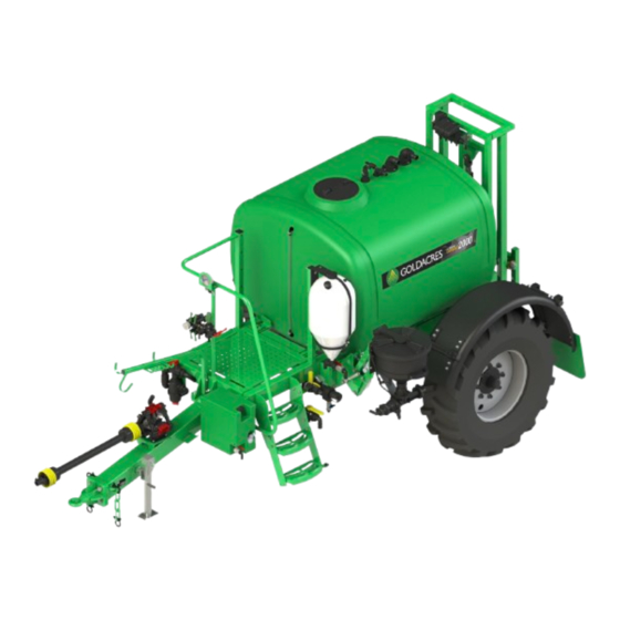
- Page 1 Prairie Compact 2000L Operator’s Manual MY19 SEE INSIDE COVER GA8701141 REV 1 JAN 2020 FROM SERIAL #P20792...
- Page 2 All information in this operator’s manual is based on the latest product information available at the time of printing. The policy of Goldacres is one of continuous improvement and as such, Goldacres reserve the right to alter any specifications and designs without notice and without incurring any obligation regarding such changes.
- Page 3 (a) the supplying of the services again; or date of the Purchaser’ s or user’ s use of the Goods and Goldacres shall be under no liability for damages arising out of the use of any (b) the payment of the cost of having the services supplied again.
-
Page 5: Table Of Contents
Contents 1 INTRODUCTION Suction Filter Cleaning ....Pressure Filter Cleaning ....Welcome . -
Page 7: Introduction
We are pleased to welcome you as a Goldacres owner and look forward to making your spray applications as efficient as possible. Please use this comprehensive resource to gain a full understanding of your equipment, and don’t hesitate... - Page 8 2 - Chapter 1 - Introduction Prairie Compact 2000L Operator’s Manual MY19 - REV 1...
-
Page 9: Safety
Goldacres in writing. The following pages outline important safety • Inspect the equipment thoroughly for damage and information. At Goldacres safety is a high priority. wear before operation. These safety and warning instructions MUST be followed to ensure the safe operation of your •... - Page 10 PPE to use with the chemical/s you are using. tank of water. Machine damage can result if the Goldacres also suggests that you read and understand machine is over weight. See filling instructions in the following Australian standards: Chapter 8 ‘Operation’...
- Page 11 Safety Information Stored Energy Hazard Empty the spray tank where possible. Chock all wheels that remain on the ground. Even when the machine is not operating, energy Securely lift the machine using a jack and support can be stored in components such as hydraulic the machine on work stands.
- Page 12 All operators should be trained in the safe use of Ag chemicals. Goldacres suggest that a relevant course is completed by owners/operators prior to operation of this equipment as a spray unit.
-
Page 13: General Information
This sprayer comes with an in cabin switch box welded for superior strength. The chassis is grit controller for controlling up to 4 boom valves. blasted, primed and then protected by the Goldacres Boom Nozzle Control paint process for excellent chemical resistance and... - Page 14 The TeeJet & Lechler nozzle selection Hydraulics catalogue and user’s guides to spray nozzles are available from your Goldacres dealer, or as a free The sprayer is supplied with one set of tractor download from the TeeJet web site: www.teejet.com remotes for the boom lift function.
-
Page 15: Wheels & Tyres
Wheels & Tyres All tyres used on Goldacres sprayers have been NOTE: If a tyre is replaced with a different brand designed to carry the maximum loaded weight of or size, please contact the supplier for correct air the sprayer when travelling at 20 km/h. The load... -
Page 16: Dimensions
ANGULAR ± 0.50° WEIGHT: ± 0.5 1392.21 KG 0.00 ± 0.25 THIS DRAWING REMAINS THE PROPERTY DEBURR AND OF GOLDACRES TRADING PTY LTD AND IS SHARP ED SUBJECT OF COPYRIGHT 2459 MATERIAL DRAWN BY: 1-3 MORANG CR. MITCHELL PARK. UNLESS OTHERWISE SPECIFIED MATERIAL <NOT... -
Page 17: Identification & Parts Ordering
Dealers are not liable for DESCRIPTION DATE / INITIAL BOM Updated 4/12/2019 JM the return of any goods to a Goldacres Dealer. The goods must be returned to the point of sale. Genuine Goldacres parts only should be used on Goldacres equipment. Serial... - Page 18 12 - Chapter 3 - General Information & Specs Prairie Compact 2000L Operator’s Manual MY19 - REV 1...
-
Page 19: Cabin
Chapter 4 CABIN Not Applicable Chapter 5 DRIVETRAIN Not Applicable Prairie Compact 2000L Operator’s Manual MY19 - REV 1 Chapter 4 & 5 - N/A - 13... - Page 20 14 - Chapter 4 & 5 - N/A Prairie Compact 2000L Operator’s Manual MY19 - REV 1...
-
Page 21: Calibration
Chapter 6 CALIBRATION Manual Rate Control - Calibration Spraying is a complex task, that is affected by many variables. It is the responsibility of the operator to be familiar with spraying variables and to understand the spraying process prior to operation. In general, the operator should know: •... -
Page 22: Nozzle Calibration
Nozzle Calibration As part of your daily sprayer calibration, Goldacres • TeeJet advise that nozzles that flow greater than recommends you carry out a simple “jug test” to +10% of their stated volume are ‘worn out’ and ensure the spray nozzles you are using are delivering should be replaced. -
Page 23: Pre-Operation
Chapter 7 PRE-OPERATION Drawbar Connections The standard drawbar connections are as shown below. It is important that the dielectric grease (supplied with each sprayer) is applied to electrical connections prior to connection. This keeps the electrical terminals in good condition by preventing corrosion. -
Page 24: Tractor Connection
Tractor Connection Prior to tractor to sprayer connection, it is important Connect drawbar connections. that the operator has read and fully understood this All hydraulic hoses except two, have a tag zip tied to operator’s manual. them that denotes what they are for. Connect the TRACTOR TO SPRAYER CONNECTION hoses to the appropriate place on the tractor. -
Page 25: Pto Shaft Fitment
PTO Shaft Fitment Wide angle PTO shafts are fitted as standard to Prairie Evolution sprayers. When using/hitching a sprayer (especially for the first time) the following critical points concerning the PTO shaft must be considered: MAXIMUM PTO OPERATING LENGTH Try to obtain the greatest possible overlap. In its working position, the PTO shaft must not be extended by more than half the profile overlap (Pu) available when fully compressed (Lz). -
Page 26: Switch Box Mounting
Switch Box Mounting The mounting of the switch box within the cabin of your tractor is a critical part of the set up process. It is important that the switch box is mounted in the cabin in such a way that it cannot cause harm to the operator under any circumstance while also being mounted in a user friendly way. -
Page 27: Wiring Schematic
Wiring Schematic Prairie Compact 2000L Operator’s Manual MY19 - REV 1 Chapter 7 - Pre-Operation - 21... -
Page 28: Plumbing Schematic
Plumbing Schematic 22 - Chapter 7 - Pre-Operation Prairie Compact 2000L Operator’s Manual MY19 - REV 1... -
Page 29: Operation
18/12/2019 GA6500020 DRAWING CHECKED BY: THIS DRAWING REMAINS THE PROPERTY DEBURR AND BREAK Spray pump OF GOLDACRES TRADING PTY LTD AND IS SHEET 1 OF 7 SHARP EDGES DO NOT SCALE DRAWING SUBJECT OF COPYRIGHT Jack Control fill & pressure manifold... -
Page 30: Ez Control
EZ Control NUMBER FEATURE Manifold Pressure Gauge Spray Pressure Line Agitator Hopper Venturi Pressure Adjuster PRESSURE DELIVERY Hopper Turn ON to use induction hopper Venturi Turn ON to use Transcal or chemical probe Agitator Turn ON to activate agitator Pressure Adjuster Used to adjust manifold pressure Manifold pressure gauge Indicates the manifold pressure... -
Page 31: Tank Filling
Tank Filling EZ Control External Water When filling the sprayer it is necessary to connect to an external water source. Delivery Station The external water delivery station allows several The main tank should be filled through the 3” fill filling functions of the sprayer to be performed point mounted to the side of the EZ control station simultaneously. -
Page 32: Agitation
Agitation TO AGITATE WHILE STATIONARY 5. If the tank has been filled and the spray mixture has been allowed to settle, agitate for as long as it Add 20 percent of the main tank’s volume in takes the pump to pump the quantity of water in fresh water to the main tank. -
Page 33: Chemical Induction Probe
ITEM NO. PART NUMBER DESCRIPTION QTY. GA5013603 PVC pipe 25mm cut 630mm HOS25PVC PVC hose 25mm cut 3.2m Chemical Induction Probe HB100-90 Hose barb 90 degree 1" Banjo Overview 100E Male Adapter 1" Hose Shank GA5018319 Ball valve 25mm FF Lever A simple method of transferring chemical into the via the chemical probe. - Page 34 Chemical Induction Probe Operation Once chemical has been transferred into the main spray tank the sprayer should always be WARNING: It is critical that the chemical probe agitating until spraying begins. venturi continues to operate for a minimum of 30 seconds following use. This will ensure that no chemical is left in the line prior to the probe being disconnected.
-
Page 35: Chemical Induction Hopper
Chemical Induction Hopper Overview The Chemical Induction Hopper is an alternative method of transferring chemical into the main spray tank. The hopper can be lowered to a more convenient height for adding chemicals. The chemical can either be in liquid form or granular form and once in the hopper the chemical can then be easily transferred into the main spray tank. - Page 36 Chemical Induction Hopper Operation • Raise the hopper to its transport position and replace the retaining pin and ‘R’-clip in the 1. Add at least 500 litres of clean water to the main mechanism. spray tank. Initially there needs to be a sufficient Rinsing amount of water in the tank in order for the pump delivery to create the venturi effect via the...
- Page 37 Chemical Induction Hopper RINSING OUT THROUGH DRAIN The hopper can be rinsed and the rinsate emptied through the hopper drain ball valve rather than transferred into the main spray tank. CAUTION: Spray pump should be turned off. To do this: 1.
-
Page 38: Manual Rate Control - Spray Application
Manual Rate Control - Spray Application After completing the filling process, you are now ready to start spraying. While travelling from the fill station to the field, the pump should be running at 400 - 500 rpm with the agitator running in order to ensure that the chemical mix is adequately agitated prior to spraying. - Page 39 Above: In cab section control and pressure regula- be set so that the pressure can not exceed 690 kPa tion control box and harness. (100 PSI). This is a Goldacres factory preset. Prairie Compact 2000L Operator’s Manual MY19 - REV 1 Chapter 8 - Operation - 33...
-
Page 40: Suction Filter Cleaning
Suction Filter Cleaning The suction filter tap is plumbed before the filter housing. The suction filter receives fluid from either the rinse water tank or the main spray tank. Therefore, all fluid to be sprayed or flushed through the system passes through this filter. NOTE: Running the main spray pump dry will damage it. -
Page 41: Pressure Filter Cleaning
Pressure Filter Cleaning There is an in-line pressure filter in the spray pressure line that traps the minute particles that are not collected by the main suction filters. WARNING: Always wear the recommended personal protective equipment and use caution while working with chemicals. Unscrew the filter body. -
Page 42: Decontamination
Decontamination Decontamination of your spraying equipment is 6. Turn off all taps to allow the pressure relief valve important when changing chemicals or application to blow off and purge the ‘relief to tank’ line. methods. 7. Operate induction equipment (if fitted), with a Information specific to your circumstances, the quantity of fresh water in order to flush venturi spraying equipment being used and the chemicals... -
Page 43: End Of Day
End of Day At the end of the spraying day: Follow the flushing 3. Remove drawbar pin. and decontamination procedure as per previous 4. Remove safety chains. instructions. 5. Disconnect all drawbar connections between the 1. Unfold the boom in an area convenient to sprayer and the tractor (i.e. -
Page 44: Plumbing Schematic
Plumbing Schematic 38 - Chapter 8 - Operation Prairie Compact 2000L Operator’s Manual MY19 - REV 1... -
Page 45: Boom
Chapter 9 BOOM NOTE: See “Small Booms 3-12m” operator’s & parts manual for details. Prairie Compact 2000L Operator’s Manual MY19 - REV 1 Chapter 9 - Boom - 39... - Page 46 40 - Chapter 9 - Boom Prairie Compact 2000L Operator’s Manual MY19 - REV 1...
-
Page 47: Lubrication & Maintenance
Chapter 10 LUBRICATION & MAINTENANCE Maintenance Schedule FREQUENCY MAINTENANCE TASKS 8 hour Check pump oil level & condition 8 hour Check tyre pressure 8 hour Check wheel nuts are torqued correctly to 320 ft/lb 8 hour Grease tilt arm pivot pins 8 hour Grease cable drum bearing block pivots 8 hour... -
Page 48: Lubrication
Lubrication Goldacres recommend that a quality multi purpose The pictures below outline key lubrication points. All grease should be used when lubricating your hydraulic cylinders (excluding wing tilt cylinder) have equipment. grease points on the clevis ends. A SAE 30W40 engine oil should be used in the diaphragm pump. -
Page 49: Maintenance - General
This will ensure a very relief setting. Goldacres pre-sets the pressure to even and constant pressure delivery. approximately 110 PSI and this should not be altered. - Page 50 Maintenance - General 3 MONTHS • Make sure the wheel is in a satisfactory condition Grease the jack; there are two grease nipples on to use and that the tyre is inflated to the correct the sprayer’s jack. One on the winding mechanism tyre pressure.
- Page 51 Maintenance - General Filters 4. Remove screen and clean. CAUTION: Read and heed the chemical label 5. Check for damage to screen, bowl, body and warnings regarding PPE before cleaning any filter. O-ring. If in-line filters have been fitted to replace nozzle 6.
-
Page 52: Corrosion Prevention
Corrosion Prevention Goldacres are applying G15 anti corrosion spray to Use the following as a guide for areas to spray with all fasteners (bolts, washers and nuts) and zinc plated corrosion inhibitor. This guide is not necessarily components at the time of manufacture. - Page 53 Corrosion Prevention DESCRIPTION DESCRIPTION Towing eye bolts LH pod frame mounting bolts Jack mounting bolts & locking pins Induction hopper bolts & latches Spray pump Mudguard mounting bolts Steps & hand rails Wheel nuts H-frame & handrails Axle bolts Boom rests Rinse tank frame mounting bolts DESCRIPTION DESCRIPTION...
- Page 54 48 - Chapter 10 - Lubrication & Maintenance Prairie Compact 2000L Operator’s Manual MY19 - REV 1...
-
Page 55: Troubleshooting
The following troubleshooting information is shown in this chapter prior to calling your dealer, or provided as a reference when your sprayer is not Goldacres, for service advice functioning correctly. To ensure that you receive Parts information and schematics can be found in the best possible service, it is recommended that the parts manual supplied. - Page 56 Spray Pump PROBLEM COMMON CAUSES COMMON SOLUTION Verify console calibration settings. Check for restriction in bypass line. Pressure and flow Bypass line is restricted or rate are too high blocked.. Check pump speed is not too fast. Check if Bypass valve is turned on The pressure on Blocked filters of nozzles Check and clean all pressure and nozzle filters...
-
Page 57: Plumbing
Plumbing PROBLEM COMMON CAUSES COMMON SOLUTION Check all wiring and connections to ensure Insufficient power. there is 12 volts at the valves. Boom valves fail to open System pressure greater than Reduce the system pressure 150 PSI. Check all wiring and connections to ensure Insufficient power. -
Page 58: Flow Meter & Controller
Chemical Probe PROBLEM COMMON CAUSES COMMON SOLUTION Air leak in the vacuum Check all hose clamps and fittings are tight system Chem probe is not working or is working too slow Lack of pressure to venturi in Check there are no kinked hoses and the top of tank water pressure is about 100 PSI ISOLATING POSSIBLE AIR LEAKS... -
Page 59: Optional Accessories
Chapter 12 OPTIONAL ACCESSORIES Not Fitted Prairie Compact 2000L Operator’s Manual MY19 - REV 1 Chapter 12 - Optional Accessories - 53... - Page 60 54 - Chapter 12 - Optional Accessories Prairie Compact 2000L Operator’s Manual MY19 - REV 1...
-
Page 61: Transcal
Prairie Compact 2000L Operator’s Manual MY19 - REV 1 Chapter 12 - Optional Accessories - 55... -
Page 62: Delta Boom
www.goldacres.com.au...
Need help?
Do you have a question about the Prairie Compact 2000L MY19 and is the answer not in the manual?
Questions and answers