Advertisement
Advertisement

Related Manuals for Goldacres Salvarani TF-EV 24


Summary of Contents for Goldacres Salvarani TF-EV 24
- Page 1 Foam Marker Kit Salvarani TF-EV 24 Operator’s Manual GA8700733 Rev0 NOV 2016...
-
Page 2: Table Of Contents
Please note: All information in this operator’s manual is based on the latest product information available at the time of printing. The policy of Goldacres is one of continuous improvement and as such, Goldacres reserve the right to alter any specifications and designs without notice and without incurring any obligation regarding such changes. -
Page 3: Foam Marker
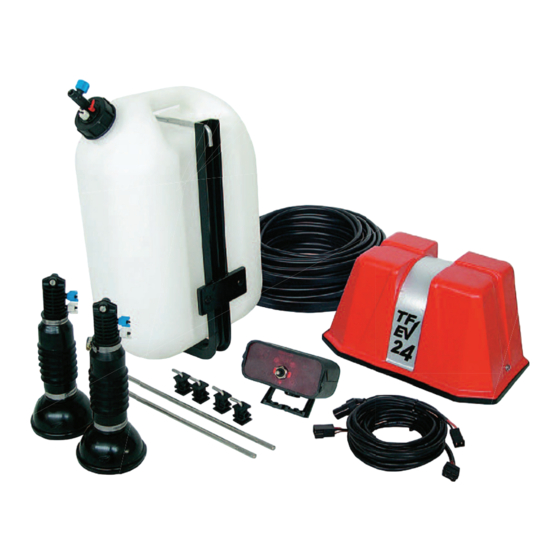
Foam Marker Use & Maintenance 1. 1-Air compressor 12 V.D.C 2. Distributors with electrovalves 3. Liquid foaming agent tank 4. Tank frame 5. White tube air 6. Blue tube liquid 7. Foam diffusers for foam formation 8. Control panel 9. Cap with safety valve Introduction Foam Marker Description (Fig . - Page 4 Liquid Foaming Agent Tank (Fig . 2) Compressor Block (Fig . 3) The tank contains the solution created by It supplies the necessary pressure to the unit water and the foam solution (Fig.2-1). It to generate the foam bubbles. The group has a cap with safety valve which limits the includes the CM 40 membrane compressor maximum pressure inside the tank at 0,75 bar...
- Page 5 Fig. 5 FUSE 20A FUSE IST 052 Control Panel (Fig . 5) Technical Data Table It allows to select (Fig.5-1) the side from which the foam bubble will exit. The feeding cable Feeding voltage 12÷14 Vdc (Fig. 5 -2) and the connection cable to the Absorbed current 9,5 A compressor (Fig.5-3) are included.
- Page 6 Fig. 18 Liquid Liquid Liquid Salvarani 15 PSI PRESS. 1 BAR (25 cm) (50 cm) Fig. 16...
-
Page 7: Installation Foam Marker
Installation Foam Marker Air and Liquid Connection (Fig . 18) You should start with the foam diffuser more Before installing the equipment, read distant from the compressor group; lay the the general rules (Chp . 4) . pipe along the frame of the spraying boom, abounding where there are joints (Fig. - Page 8 Fig. 9 Fig. 8 Liquid TF-EX Fig. 19 Black Brown Black Brown Black Black Brown Black FUSE 20A Black Brown Schema elettrico 3-4 elettrovalvole - electric scheme 3-4 electrovalves - plan électrique 3-4 electrovannes - elektrisches Schema 3-4 lektroVentile - conexion electrica 3-4 electrovalvulas...
-
Page 9: Use Of Foam Marker
flow regulator (Fig.9 -1), to be positioned using the min-max regulator on the ERIA NERA on the compressor or on the cap (Fig. 9 ref.1). screws and fixing clamp Activate the selector on the control box to activate the right or left row of the while on demand the controller/computer equipment interface. - Page 10 Operations to be carried out annually machine, above all with high pressure pumps (Fig.17). It is necessary to substitute the Fig. 17 sponges inside the foam diffuser/ mixer annually (Fig. 13) disassemble the foam diffuser in its parts, taking care to remove elastic containment net (Fig 13-3) with a plier;...
-
Page 11: General Rules Of Foam Marker
Fig. 12 uncouple the tube (Fig 12-3) by if necessary substitute the damaged or faulty unscrewing the connection(Fig 12-2) connector. Maintenance of the compressor Check also that the connection tubes between The compressor does not require lubrication . compressor, tank and foam diffuser/mixer are not damaged and that all the connections To substitute the membrane proceed as have a perfect pressure holding;... - Page 12 Packing must be disposed of by the when there is zero voltage. user according to the current laws of 4.g Check that machine operation and each the country . of its blocks, even auxiliary does not 12 V.DC During the unpackaging and handling trigger off situations of danger to people or things.
- Page 13 Fig. 13 Fig. 14 Fig. 15 OPTIONAL...
- Page 14 Defects Causes and Solutions Check the fusible. Check the exact electrical contact and The compressor block does not the connection of the socket in the plug. After long periods work Fig.3 of inactivity the small motor can block. To unblock it provoke a vibration and spray some deoxidizer in the brushes.
-
Page 15: Parts
Parts Part No Description GA8700420 Foam Accumulation Complete GA8700421 Needle Valve GA8700422 Lid, Needle Valve and pick up tube assembly GA5078421 GA5078420 GA5078422... -
Page 16: Goldacres
1-3 Morang Crescent, Mitchell Park Vic 3355 P: 03 5342 6399 F: 03 5342 6308 info@goldacres.com.au goldacres.com.au...
Need help?
Do you have a question about the Salvarani TF-EV 24 and is the answer not in the manual?
Questions and answers