
Related Manuals for National Flooring Equipment 7700-EUR


Summary of Contents for National Flooring Equipment 7700-EUR
- Page 1 7700 ALL-DAY BATTERY RIDE-ON SCRAPER OPERATING & SERVICE MANUAL Read Manual Before Operating or Servicing Machine 401836 Rev K...
-
Page 3: Table Of Contents
Table of Contents Table of Contents ................................3 Features and Specifications ............................4 Safety ....................................6 General Rules For Safe Operation ........................6 Ride-On Scraper Safety Guidelines ........................7 Hydraulic Safety ..............................8 Components and Assembly ............................9 Charger Instructions .............................. 9 Machine Charging .............................. -
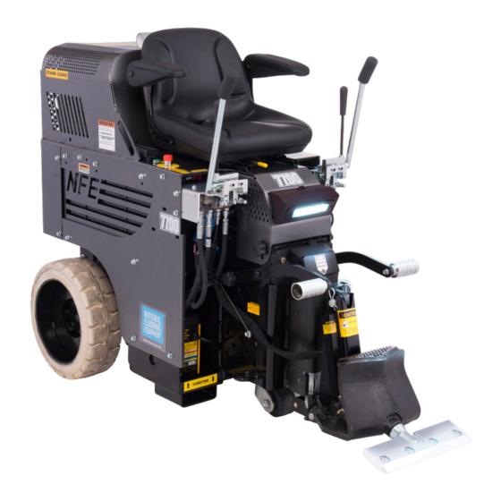
Page 4: Features And Specifications
Features and Specifications Control Levers Adjustable Arm Rests Seat Switch Headlight DC Motor Pump Compartment Adjustable Slide Plate Adjustable Foot Rests 18” Wheels Cutting Head Onboard Battery Cylinder Lift Charger Forklift Cups Debris Deflector Swivel Cutting Head FEATURES Seat Switch - Ensures the machine will not function without someone DC Motor Pump Compartment - Provides easy access to the motor in the operator seat. - Page 5 Features and Specifications Product Specifications Weight Weight Width Length Height Removable Weight (Machine Only) (Fully Weighted) 29.5” 58.5” 51” 2,572 lb 2,757 lb 185 lb (75 cm) (161 cm) (130 cm) (1,167 kg) (1,250.6 kg) (83.9 kg) Power Max. Speed Sound Level 4 HP 200 ft/min.
-
Page 6: Safety
Read the manual carefully to learn equipment applications and limitations, as well as potential hazards associated with this type of equipment. Keep manual near machine at all times. If your manual is lost or damaged, contact National Flooring Equipment (NFE) for a replacement. Personal Maintenance &... -
Page 7: Ride-On Scraper Safety Guidelines
Safety RIDE-ON SCRAPER SAFETY GUIDELINES Scraping Charger Operation Do not drive machine along hills or uneven surfaces. Ensure proper use of charger. The weight of the machine may become distributed differently if on • Once connected and plugged into AC power, the LED will in- an uneven surface. -
Page 8: Hydraulic Safety
Safety HYDRAULIC SAFETY Maintaining a Safe Work Environment Establishing a safe work environment in and around your hydraulic equipment is extremely important. The easiest and most effective way to avoid problems is to make sure associates understand their equipment, know how to operate the machines safely, and recognize the dangers if handled carelessly. -
Page 9: Components And Assembly
Components and Assembly CHARGER INSTRUCTIONS See Ride-On Safety Guidelines for charger safety and instructions. Before making AC connections, refer to the requirements on the charger ID label. This battery charger must be grounded to reduce the risk of electric shock. Chargers are equipped with a grounding type plug. -
Page 10: Transport
Components and Assembly TRANSPORT • Secure machine with ratchet straps during transport. Proper securing straps need to be rated at least twice the weight of the machine. • Chock wheels to keep machine from rolling, but do not use them on their own. •... -
Page 11: Cutting Head And Blades
Components and Assembly Transport Wheels The front wheel assembly is included and very helpful when moving a machine around on a jobsite or loading a machine that is not on a pallet. It allows machine stability and safe transportation over most surfaces. It is quick and easy to attach or detach. Raise slide plate so the bottom of the slide plate is higher or even with the bottom of the guide channels, 6”-8”... - Page 12 Components and Assembly Swivel Head Blade Securing Bolt Cutting Head The swivel head keeps the blade in contact with the floor even when the floor is uneven. When using a flat blade, turning the head over 180° provides another sharp edge on the blade without having to replace the blade.
-
Page 13: Foot Pegs
Components and Assembly Blade Setting • Proper blade size and placement, depending on material and sub-floor type, af- Bevel Up fects performance. • For better results during difficult removal applications use a smaller blade. • Start with a narrow blade, then increase blade size to optimize cutting pass. Nar- rower blades work easier than wider blades and usually clean the floor better. -
Page 14: Operation
Operation OPERATING CONTROLS Power On Button/Key (Figure 12) Never use the Power On button/key as a method for speed control. Speed control is achieved by the hydraulic valve only. Using the On/Off switch repeatedly will cause excessive wear and premature failure of electrical components. Hydraulic Levers (Figure 13) International Domestic... -
Page 15: Shut-Down Procedure
Operation SHUT-DOWN PROCEDURE The machine will stop when the operator is no longer seated, or when the emergency stop is engaged. Remove blade or drop cutting head to the floor when machine is not in use. SLIDE PLATE ADJUSTMENTS AND SETTINGS Dual Lift (Figure 17) Prior to adjusting the dual lift hydraulic slide plate, make sure the channel guide is free of FIG. - Page 16 Operation Wood The slide plate should be adjusted to a low setting 1” (2.5 cm) off the floor. Use shank blades, shank blades with carbide tips, or a 6” or 8” (15- 20 cm) cutting head with heavy duty blades. Note: Run machine 45°...
-
Page 17: Ditching
Operation Soft Sub-Floor Tile Ditch 1’-2’ 2”-6” The slide plate should be adjusted to a low setting 1” (2.5 cm) off the floor. Blades should CROSS-ROOM DITCHING Strips Blade be as flat of an angle as possible. Use a heavy duty blade (these blades have a bend to them) or a regular blade bevel down. -
Page 18: Maintenance Schedule
Maintenance Schedule Interval After initial After initial Maintenance to be performed Daily 200 hrs 1000 hrs 2000 hrs 100 hrs 500 hrs Inspect extension cord for damage ● Check wheels, caster and wheel motors for build up; and clean ● Inspect all safety devices (e-stop, backup beeper, seat switch) ●... -
Page 19: Troubleshooting Guide
Troubleshooting Guide Problem Cause Solution Machine will not start. Seat safety switch is disengaged. Ensure operator is seated. Emergency stop (E-Stop) switch is disen- Twist E-Stop so that it is in the “POWER ON” gaged. position. Circuit breaker is in the “OFF” position. Verify circuit breaker is in “ON”... -
Page 20: Maintenance
Maintenance WARNING: ALWAYS DISCONNECT BATTERY BEFORE PERFORMING MAINTENANCE. DUAL SLIDE PLATE REMOVAL WARNING: ASSEMBLY IS VERY HEAVY. USE TEAM LIFT OR FORKLIFT TO LIFT. KEEP HANDS AND FEET OUT FROM UNDER THE ASSEMBLY. FAILURE TO DO SO COULD CAUSE SEVERE INJURY. Lower the slide plate to the floor and place a wood block under the assembly. -
Page 21: Change Hydraulic Cylinder
Maintenance CHANGE HYDRAULIC CYLINDER Disconnect machine from power. Disconnect cylinder lines. Have a container ready to catch oil from lines. Remove cylinder securing hexhead bolt from lower cutting head support. Remove clips and pin from cylinder and slide plate. Remove cylinder upper pin. Remove cylinder. -
Page 22: Change Rear Wheel
Maintenance CHANGE REAR WHEEL (FIG. 1) Jack machine up by pushing the cylinder lift forward to lower and adjust the angle of the cutting head to raise machine. Place blocks under forklift cups on the side of the machine that wheel is being changed. -
Page 23: Remove/Replace Foot Peg
Maintenance REMOVE/REPLACE FOOT PEG Insert a socket wrench into foot peg and secure bolt head. Remove nut. Remove bolt and foot peg. Replace foot peg before operating machine. Do not operate machine without foot pegs. CLEAN WHEEL MOTOR BUILD-UP Inspect the wheel motor and wheel motor hub for debris build-up (best accessed from back of machine). Remove any strands of carpet and use compressed air (not high pressure) to clean out dust or glue build-up. -
Page 24: Parts List And Diagrams
Parts List and Diagrams EXTERNAL PARTS 7, 8 PART# DESCRIPTION PART# DESCRIPTION 1 N/A SEE REAR WHEEL ASSEMBLY 404304-G HINGE, LOWER, BOLT-ON, LOWER WRAP, 2 N/A SEE CHARGER ASSEMBLY GREEN (7700-12XXXX ONLY) 3 5200-603 GUIDE, HOSE 404304-O HINGE, LOWER, BOLT-ON, LOWER WRAP, 4 401999 KNOB, ADJUSTABLE, 3/8 X 3/4 ORANGE (7700-15XXXX ONLY) - Page 25 Parts List and Diagrams REAR WHEEL ASSEMBLY ITEM PART NUMBER DESCRIPTION QTY. 400133 Motor, Wheel, Hydraulic, 10mm 73047 Key, Woodruff 5/16 x 1 73402 Nut, Nylock 1/2-13 5110-117 Wheel, Hub 73430 Nut, NyLock 1/2-20 5600-300 Wheel, Rim and Tire, 18" 5110-117-2 Hub Nut 401433...
- Page 26 Parts List and Diagrams HOOD BUMPER ASSEMBLY PART# DESCRIPTION 1 73070 BOLT, SOCKET HEAD CAP, 1/4-20X1 2 5600-66 BUMPER, HOOD WEIGHTS PART# DESCRIPTION 1 74854 WEIGHT, POCKET, CAST, RIDE ON 2 73424 WASHER, FLAT, ZINC SAE 5/8 3 73403 WASHER, SPLIT LOCK 1/2 4 73414 BOLT, HEX HEAD 1/2 13X7 5 73531...
- Page 27 Parts List and Diagrams SPOOL AND HOSE PARTS PART# DESCRIPTION 1 400003 HOSE, HYDRAULIC, 3/8 X 39, F/90LF 2 5700-72 HOSE, HYDRAULIC, 3/8 X 21, F/F 3 5700-76 HOSE, HYDRAULIC, 3/8 X 26, F/F 4 SEE CONTROL LEVER PARTS 5 SEE GEAR PUMP ASSEMBLY 6 400002 HOSE, HYDRAULIC, 3/8 X 39, F/90F FILTER AND TANK PARTS...
- Page 28 Parts List and Diagrams SUCTION ASSEMBLY PART# DESCRIPTION PART# DESCRIPTION 1 5700-77 ASSEMBLY, HOSE 7 70655 PIPE, MALE, 10” X 3/4 2 5700-81 HOSE, SUCTION LINE 8 5700-93 GASKET 3 5700-67 PLUG, TANK 9 400099 HOSE, SUCTION, 1/2” X 20” W/ FITTING 4 70653 FITTING, 90 DEGREE 10 5110-237...
- Page 29 Parts List and Diagrams GEAR PUMP ASSEMBLY PART# DESCRIPTION 1 70905-D7 PUMP, DOUBLE, MARZOCCHI 2 5200-1G GASKET, PUMP 3 72816 FITTING, ELBOW, 90 DEGREE, 3/8” 4 6280-118 FITTING, SUCTION HOSE TO PUMP 5 73263 WASHER, FLAT SEA ZINC 3/8 6 73204 WASHER, SPLIT LOCK 3/8 7 403626 SCREW, FERRY CAP, 3/8-16 X 3/4”, 12PT 2...
- Page 30 Parts List and Diagrams CONTROL LEVER PARTS ITEM ITEM PART NUMBER DESCRIPTION QTY. PART NUMBER DESCRIPTION QTY. 402416 Assembly, Valve Handle, Right 400034 Fitting, FF1231-06-08 73320 Bolt, Socket Head Cap 5/16-18x2 401797 Bracket, Universal, Lever 401408 Spacer, Round, .323 X .625 X .675 400137 Fitting, 1/2 - 1/4, JIC 5700-60...
- Page 31 Parts List and Diagrams DUAL SLIDE PLATE ITEM PART NO. DESCRIPTION QTY. 400132 Bolt, Hex Head, 1/2-13 x 4, Grade 8 400296 Gasket, EPDM Foam 401429 Pin, Lower Cutting Head Support 401876 SSS, 3/8-24 x .25, Black Oxide 402423 Housing, Hydraulic Adjustment, Wldt 402432 Slide Plate, Hydraulic Adjustment, Wldt 402440...
- Page 32 Parts List and Diagrams ELECTRICAL BOX ASSEMBLY PART# DESCRIPTION 1 5200-118-8 CONNECTOR, BLUE 48V BATTERY 2 5700-100 WIRE SET (NOT SHOWN) 3 5700-104 SOLENOID 4 5700-106 BREAKER, CIRCUIT, 70 AMP 5 5700-85 COVER, TERMINAL STRIP 6 403129 HARNESS, MAIN 7 71703 PROTECTOR, BATTERY TERMINAL, RED 3 8 5700-90 RELAY, SOCKET...
- Page 33 Parts List and Diagrams CHARGER ASSEMBLY ITEM PART 7700-10XXXX DESCRIPTION QTY. Item 7700-11XXXX NUMBER 7700-12XXXX 7700-13XXXX 7700-20XXXX Description Qty. 7700-15XXXX Part No. 7700-23XXXX Part No. Assembly, Delta-Q Charger Replacement, 1500W, 108-250VAC, Plate, Mounting, High Frequency 403202 403202 403202 402588 Charger Hi-Freq, 370-440AH 73008 Nut, Hex, Nylon Insert, 1/4-20...
- Page 34 Parts List and Diagrams POWER CONTROLS (DOMESTIC) PART# DESCRIPTION 1 5700-103 SWITCH, START, ASSEMBLY 72451* CONTACT, NORMALLY OPEN 72454 PUSH BUTTON, GREEN 72456* COLLAR, BODY MOUNTING 2 5700-102 ASSEMBLY, E-STOP 72452* CONTACT, NORMALLY CLOSED 72453 PUSH BUTTON, RED 72456* COLLAR, BODY MOUNTING 5700-102D PLATE, EMERGENCY STOP 3 403042...
- Page 35 Parts List and Diagrams SEAT ASSEMBLY PART# DESCRIPTION 1 401631 ADJUSTER, FORE/AFT, SEAT 2 5110-111 SEAT, RIDE-ON 3 400321 ARM RESTS, KIT FOR SEAT 4 73322 NUT, NYLOC, 5/16-18 (NOT SHOWN) SEAT SWITCH PART# DESCRIPTION 1 5110-207 SWITCH, SEAT SEAT HARNESS PART# DESCRIPTION 1 403128...
- Page 36 Parts List and Diagrams BACKUP BEEPER ASSEMBLY PART# DESCRIPTION 1 5200-116 BEEPER, BACK UP 2 73020 BOLT, WIZLOCK, 1/4-20X5/8 HEADLIGHT ASSEMBLY ITEM PART NUMBER DESCRIPTION 403976 Switch, Rocker, SP, 14V, 16 A 404009 Shroud, Worklight, Rider, Low Profile 404041 Light, Work, 6"x2", Flush, 18W 404060 Screw, Button Head Cap, M5x0.8x10, Black Oxide 74631...
- Page 37 Parts List and Diagrams LABELS PART# DESCRIPTION PART# DESCRIPTION 1 405051-XX** KIT, LABELS, 7700, [LANGUAGE] L38* LABEL, DISCONNECT POWER L08-1 LABEL, STAND CLEAR L66* LABEL, LARGE CAUTION L106 LABEL, PINCH POINT L95F LABEL, FLUID LEAK L118 LABEL, OPERATOR MUST BE SEATED LABEL, BLADE LIFT 402926 LABEL, CHARGER, QUIQ1500...
-
Page 38: Wiring Diagrams
Wiring Diagrams MAIN WIRING DIAGRAM BATTERY BANK A MOTOR 4-BLK 4-BLK 4-RED MAIN NEGATIVE 16-BLK 4-RED POST 16-BLK 4-RED 10-BLK BREAKER 16-BLK MAIN 4-RED POSITIVE 16-RED CONTACTOR 10-RED POST 16-RED 16-YEL 16-BLK 16-RED 10-RED CHARGER 10-BLK TERMINAL WIRING BLOCK JUMPERS 16-BLK 14-RED 16-BLK... - Page 39 Wiring Diagrams SEAT WIRING DIAGRAM TO MAIN WIRING MODULE 20-YEL 20-YEL 20-BLU 20-BLU 20-BLK 20-BLK 20-RED 20-RED 20-RED T-W36 T-W10 16-BRN 16-RED T-W30 TW-11 E-STOP START SWITCH 16-BLU T-W34 T-W35 16-WHT SEAT SWITCH 16-BRN 16-BRN T-F31 T-F32 T-W33 LIGHT SWITCH 18-RED T-F3 T-F2...
- Page 40 Wiring Diagrams CHARGER WIRING DIAGRAM 12-GRN 115V 12-WHT 10-WHT 10-RED MAINS TO MAIN 12-BLK 10-BLK 10-BLK WIRING EXTENSION CORD CHARGER 20-WHT 16-BLK 14-BLK 16-BRN 20-BRN 16-BLK TO MAIN 14-WHT 16-BLU 20-GRN 16-YEL WIRING 14-GRN 16-GRN 20-BLU 16-ORG 20-ORG 20-RED 20-BLK 20-YEL 401836_7700_RevK...
- Page 41 Wiring Diagrams BATTERIES WIRING DIAGRAM #12 BATT #9 BATT 4-BLK 4-BLK 4-BLK 4-BLK BATTERY BANK #11 BATT #8 BATT “B” 4-BLK 4-BLK #10 BATT #7 BATT 4-RED 4-BLK 4-BLK #1 BATT #6 BATT 4-BLK MAIN NEGATIVE 4-BLK 4-BLK POST #2 BATT #5 BATT BATTERY BANK...
- Page 44 9250 Xylon Avenue N • Minneapolis, MN 55445 • U.S.A. Toll-free 800-245-0267 • Phone 763-315-5300 • Fax 800-648-7124 • Fax 763-535-8255 Web Site: www.nationalequipmentdirect.com • E-Mail: info@nationalequipment.com...
Need help?
Do you have a question about the 7700-EUR and is the answer not in the manual?
Questions and answers