Burkert 8041 Operating Instructions Manual
Insertion electromagnetic flowmeter
Hide thumbs
Also See for 8041:
- Instruction manual (40 pages) ,
- Operating instructions manual (60 pages)
Table of Contents
Advertisement
Quick Links
Download this manual
See also:
Instruction Manual
Advertisement
Table of Contents

Related Manuals for Burkert 8041


Summary of Contents for Burkert 8041
- Page 1 Type 8041 Insertion electromagnetic flowmeter Magnetisch-induktives Durchfluss-Messgerät, Insertion Débitmètre électromagnétique à insertion Operating Instructions Bedienungsanleitung Manuel utilisateur...
- Page 2 We reserve the right to make technical changes without notice. Technische Änderungen vorbehalten. Sous réserve de modifications techniques. © Bürkert SAS, 2011 - 2019 Operating Instructions 1904/04_EU-ML 00559777 / Original_FR...
-
Page 3: Table Of Contents
8.2.1. Recommendations for installing the 8041 on 5.1. Area of application ................8 the pipe ..................18 5.2. general description ................8 8.2.2. Installation into the pipe of a 8041 with a G2'' nut ..21 5.2.1. Construction ................8 8.2.3. Installation into the pipe of a 8041 with a clamp connection ................22 5.2.2. - Page 4 Type 8041 9.2. Description of the electronic board ........30 13. storAge ....................... 56 9.3. general diagram of the read and 14. DisposAl of the Device ..............56 parameterizing modes ..............32 9.4. selecting the frequency of the main supply ..... 34 9.5. filter selection ................... 34 9.6. selecting the measurement range ......... 35 9.7. calibrating the flow zero point ..........35 9.8. calibrating the full scale .............. 38 9.9. setting the parameters of the relay output ....... 41 9.9.1.
-
Page 5: About These Operating Instructions
▶ Failure to observe this warning results in death or in serious injury. 1.2. Definition of the word "device" The word "device" used within these Operating Instructions refers to Warning the flowmeter type 8041. Warns against a potentially dangerous situation. ▶ Failure to observe this warning can result in serious injury or even death. English... -
Page 6: Intended Use
The operating company is responsible for the respect of the local The 8041 flowmeter is intended exclusively to measure the flow safety regulations including staff safety. rate in liquids. ▶ Use this device in compliance with the characteristics and commissioning and use conditions specified in the contractual risk of injury due to high pressure in the installation. - Page 7 Type 8041 Basicsafetyinformation nOTiCe the device may be damaged by the fluid in contact with. various dangerous situations ▶ Systematically check the chemical compatibility of the compo- To avoid injury take care: nent materials of the device and the fluids likely to come into ▶ to prevent any unintentional power supply switch-on.
-
Page 8: General Information
The device requires an 18...36 V DC power supply and has: these Operating Instructions. • a frequency output, • a relay output, 4.3. information on the internet • a 4...20 mA current output. You can find the Operating Instructions and technical data sheets regarding the type 8041 at: www.burkert.com English... -
Page 9: Operating Principle
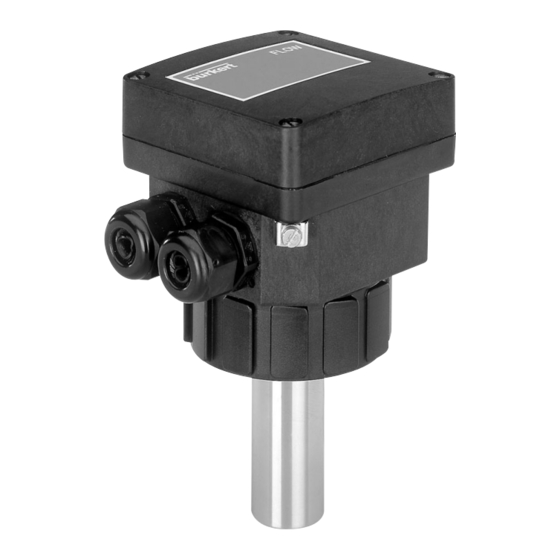
Fig. 1. The elec- trodes on the flow sensor ensure electrical contact with the fluid. FLOW: 8041 SST LONG SUPPLY: 18-36V... 220mA When the fluid flows over them, a voltage is measured between the PULSE: 5-36V... -
Page 10: Technical Data
Type 8041 Technicaldata TechnicAl DATA 6.2. conformity to standards and directives 6.1. conditions of use The applied standards, which verify conformity with the EU Direc- tives, can be found on the EU Type Examination certificate and/or Ambient temperature –10...+60 °C the EU Declaration of Conformity (if applicable). -
Page 11: Ul-Certification
Type 8041 Technicaldata 6.2.2. ul-certification part material Seal of the flow sensor The devices with variable key PU01 or PU02 are UL-certified FKM (FDA approved) (version with G2" nut) products and comply also with the following standards: • UL 61010-1 Table 2 : Parts not in contact with the fluid •... -
Page 12: Dimensions Of Device
• ±0.5 % of the full scale (10 m/s) → please refer to the technical data sheets regarding the type • Repeatability • ±0.25 % of the measured value 8041 avalaible at: www.burkert.com • Measurement deviation - with standard K-factor - ±3.5 % of the measured value... - Page 13 +150 T [°C] T (°C) Fig. 5 : Fluid pressure-temperature dependency of the 8041 with a Except DN100 for measuring devices with a clamp connection flow sensor holder in PVDF, inserted into an S020 fitting in Fig. 6 : Fluid pressure-temperature dependency of the 8041 with a...
-
Page 14: Electrical Data
Type 8041 Technicaldata 6.6. electrical data relay output To use the relay outputs in a wet location, observe the following operating voltage • 18...36 V DC, DANGER safety instruction. • filtered and regulated • non UL version • Normally open or normally closed, depending on the wiring •... -
Page 15: Electrical Connections Data
Type 8041 Technicaldata 6.7. electrical connections data The following formulae are used to calculate the K1 and K2 factors needed to convert the current or frequency into a flow rate: type of connection Through two M20x1,5 cable glands Full scale K-factor K K-factor K ▶... -
Page 16: Quick Installation
Type 8041 Quickinstallation QuicK insTAllATion → Unpack the device. → Select the measuring range with switches 4 and 5, see chap. 9.6. → Install the device on the pipe. Contact your Bürkert Article number agent correct? → Thread the cables through the... - Page 17 Type 8041 Quickinstallation No, see chap. 10.5 Green LED flashes once? Calibrate the full scale of the installation? → Put the cover on the device as described in Fig. 16, chap. 8.3. → Tighten the 4 screws of the → Calibrate the full scale, see cover in an alternating pattern.
-
Page 18: Installation
▶ Shut down the electrical power source of all the conductors and 8.2. installation onto the pipe isolate it before carrying out work on the system. ▶ Observe all applicable accident protection and safety regula- 8.2.1. recommendations for installing the tions for electrical equipment. 8041 on the pipe English... - Page 19 Type 8041 Installation → Choose a fitting appropriate to the velocity of the fluid inside the pipe; refer to the graphs below: flow rate English...
- Page 20 Type 8041 Installation → Install the device on the pipe to have the upstream and down- → Respect the following additional mounting conditions to ensure stream distances respected according to the design of the that the measuring device operates correctly: pipes, refer to standard EN ISO 5167-1 and Fig.
-
Page 21: Installation Into The Pipe Of A 8041 With A G2'' Nut
Type 8041 Installation 8.2.2. installation into the pipe of a 8041 Horizontal mounting with a g2'' nut Observe the installation recommendations described at chap. 8.2.1 and in the Operating Instructions of the S020. Correct Incorrect Vertical mounting → Install the S020 fitting (mark 4, Fig. 11) on the pipe. -
Page 22: Installation Into The Pipe Of A 8041 With A Clamp Connection
▶ Use a high quality electrical power supply (filtered and flow direction regulated). ▶ Use cables with an operating temperature limit correct for Fig. 12 : Installation into the pipe of a 8041 with a clamp connection your application. English... - Page 23 Type 8041 Installation → Protect the power supply by means of a 300 mA fuse selector : Sink/source and a switch. selector of the 4...20 mA output → Do not install the cables near high voltage or high fre- 1 2 3 4 5 6 terminal block 3 quency cables.
- Page 24 Type 8041 Installation nOTiCe make sure the installation is equipotential (power supply - 8041): the device is not tight if only one or none of the cable glands → Connect together the various earth spots in the instal- is used lation to eliminate the potential differences that may occur ▶ The device is only tight when the cable glands are either wired or between two earthes.
-
Page 25: Wiring The 4
Wiring the 4...20 mA output Power cable shield 18...36 V DC The current output of the 8041 can be connected to a PLC or a Power supply valve, either in sourcing mode or in sinking mode. → Set the selector of the electronic board to the sourcing or the sinking position (see Fig. -
Page 26: Wiring The Frequency Output
Type 8041 Installation Power supply 300 mA 4...20 mA input at external instrument 18...36 V DC Input Selector to sink 1 2 3 4 5 6 1 2 3 4 5 6 8041 4...20 V+ V- PE Pls+Pls- 4...20 V+ V- PE Pls+Pls- * If direct earthing is not possible, connect a 100 nF/50 V condensator between the negative terminal of the voltage supply and the earth. -
Page 27: Wiring The Relay Output
Type 8041 Installation 8.3.3. Wiring the relay output V+ 0V Danger Danger due to the operation of the relay outputs of a ul device in a wet location. ▶ If a UL device is used in a wet location: 1 2 3 4 5 6 8041 - energize the relay outputs with an alternating voltage of max. - Page 28 Type 8041 Installation Power supply 18...36 V DC Power supply 18...36 V DC 300 mA 300 mA 1 2 3 4 5 6 3 4 5 6 250 V AC 250 V AC 4...20 V+ V- PE Pls+Pls- 4...20 V+ V-...
-
Page 29: Adjustment And Commissioning
Type 8041 Adjustmentandcommissioning ADjusTmenT AnD Warning commissioning Danger due to non-conforming commissioning. Non-conforming commissioning can lead to injuries and damage 9.1. safety instructions the device and its surroundings. Danger ▶ Before commissioning, make sure that the staff in charge have read and fully understood the contents of these Operating Instructions. -
Page 30: Description Of The Electronic Board
Type 8041 Adjustmentandcommissioning 9.2. Description of the electronic board The device has 2 operating modes: the Read mode and the Param- eterizing mode. The functions of each mode are summarised in the following table. operating mode functions Read To view: • the fluid velocity measured by the device;... - Page 31 Type 8041 Adjustmentandcommissioning Red led: Green LED: 1 2 3 4 5 6 : device in Read mode ..4...20 V+ V- PE Pls+Pls- Flashing once every second: the device is energized. : device in Parameterizing mode Flashing once up to 5 times: to know which parameter the bargraph is indicating ..
-
Page 32: General Diagram Of The Read And Parameterizing Modes
Type 8041 Adjustmentandcommissioning 9.3. general diagram of the read and parameterizing modes read mode parameterizing mode Calibration in progress Flow zero calibration alternately Confirm the choice Hold > 2 s Release when Full scale calibration displayed desired function is displayed* Hold > 2 s * If no action for 10 s, the device goes back to Read mode, using the parameters from the previous adjustment. - Page 33 Type 8041 Adjustmentandcommissioning relay Hysteresis switching Confirm the choice displayed alternately Current way of Release when Hold > 2 s switching* Window switching desired function is displayed* Hold > 2 s Short press Current low switching ..Hold > 2 s...
-
Page 34: Selecting The Frequency Of The Main Supply
Type 8041 Adjustmentandcommissioning 9.4. selecting the frequency of the When the filter is enabled, switch 3 is used to select the filter level: slow or fast. main supply "Slow" filter is used to even out high variations in flow (example: fluid Switch 1 is used to select the frequency of the current provided by containing air bubbles), see Fig. -
Page 35: Selecting The Measurement Range
Type 8041 Adjustmentandcommissioning 9.7. calibrating the flow zero point Filter Position of switch 3 → Calibrate the device on commissioning and after each slow (Response time 10 to 90 % = 14 s) maintenance task. • Before calibrating the zero point on commissioning:... - Page 36 Type 8041 Adjustmentandcommissioning Device in Read mode? Notation convention: See general configuration diagram, chap. 9.3 ..Red LED state Green LED state → Press and hold the push button. After 2 s, device is in Parameterizing mode: ..Step 1...
- Page 37 Type 8041 Adjustmentandcommissioning to calibrate automatically to select the calibration of the to go back to the read mode other parameter → Briefly press push button. → Wait for 10 s. → Press and hold the push button until... Go back to Read mode Calibration in progress ...bargraph goes back to step 1, without confirming the Fig.
-
Page 38: Calibrating The Full Scale
Type 8041 Adjustmentandcommissioning 9.8. calibrating the full scale Full scale error The Fig. 29 and the Fig. 30 show the relation between the measured fluid velocity and the value of the frequency or current provided by the outputs. Full scale error... - Page 39 Type 8041 Adjustmentandcommissioning Device in Read mode? Notation convention: See general configuration diagram, chap. 9.3 ..Red LED state Green LED state → Press and hold the push button. After 2 s, device is in Parameterizing mode: ..Step 1...
- Page 40 Type 8041 Adjustmentandcommissioning to calibrate automatically to select the calibration of the to go back to the read mode other parameter → Briefly press push button. → Wait for 10 s. → Press and hold the push button until... Go back to Read mode without con- Calibration in progress firming the selection displayed..bargraph goes back to step 1, Fig.
-
Page 41: Setting The Parameters Of The Relay Output
Type 8041 Adjustmentandcommissioning 9.9. setting the parameters of the relay output The Fig. 33 shows the behaviour of the relay output depending on the parameter settings and the measured velocity. High threshold Low threshold Connection of the relay output Relay... -
Page 42: Choosing The Switching Way Of The Relay Output
Type 8041 Adjustmentandcommissioning The wiring of the relay determines the function of the relay: State of the relay output Normally Open (NO) or Normally Closed (NC). actived The following parameters of the relay output can be set: deactivated - the switching way: window or hysteresis (see chap. 9.9.1) - Page 43 Type 8041 Adjustmentandcommissioning State of the relay output See general con- Device in Read mode? actived figuration diagram, ..chap. 9.3 deactivated Low threshold High threshold → 1 short press on push button. Fig. 37 : Change of state of the relay output in hysteresis switching with a relay wired as NC →...
-
Page 44: Viewing And Setting The Low And High Switching Thresholds
Type 8041 Adjustmentandcommissioning → Release push button when bargraph shows desired way of switching. to confirm the selection and go back to choose the other way of switching to go back to read mode without to read mode confirming the selection → Press and hold the push button → Briefly press push button. → Wait for 10 s. until... Go back to Read mode Go back to Read mode ...bargraph goes back to step 1,... - Page 45 Type 8041 Adjustmentandcommissioning Device in Read mode? Notation convention: See general configu- ration diagram, chap. 9.3 ..Red LED state Green LED state FS = Full scale to view low switching threshold to view high switching threshold → Press push button twice briefly → Press push button three times briefly...
- Page 46 Type 8041 Adjustmentandcommissioning If high switching threshold set to 82 %, LED no. 9 If low switching threshold set to 24 %, LED no. 3 flashes 9 times then stays on; flashes 9 times then stays on; 1 flash = 1 % of the FS...
-
Page 47: Viewing And Setting The Time Delay Before Switching
Type 8041 Adjustmentandcommissioning to confirm the selection and go to modify the value displayed to go back to read mode back to read mode without confirming the value set. → Press and hold the push → Briefly press push button. button → Wait for 10 s. → Release the push button Go back to Read mode when desired number of Go back to Read mode LEDs is on .. - Page 48 Type 8041 Adjustmentandcommissioning Notation convention: ..Red LED state Green LED state If time delay before switching set to 52 s, LED no. 6 flashes 9 times then stays on Device in Read mode? See general con- figuration diagram, ..
- Page 49 Type 8041 Adjustmentandcommissioning to go back to read mode without to modify the seconds of the to go back to read mode without confirming the value set. time delay before switching. confirming the value set. → Briefly press push button. → Press and hold the push → Wait for 10 s. button → Release push button when LED has flashed the desired number of times Fig. 45 : Setting the time delay before relay switching, part 3...
-
Page 50: Maintenance And Troubleshooting
Type 8041 Maintenanceandtroubleshooting mAinTenAnce AnD Warning TroubleshooTing risk of injury due to non-conforming maintenance. ▶ Maintenance must only be carried out by qualified and skilled 10.1. safety instructions staff with the appropriate tools. Danger ▶ Guarantee a set or controlled restarting of the process subse- quent to any intervention. -
Page 51: Replacing The Seal On A Device With G2" Nut
Type 8041 Maintenanceandtroubleshooting 10.4. replacing the seal on a device 10.5. if you encounter problems with g2" nut Danger nOTe risk of injury due to high pressure in the installation. Do not scratch the seal groove. @ ▶ Stop the circulation of fluid and cut off the pressure before loosening the process connections. risk of injury due to electrical voltage. ▶ Shut down the electrical power source of all the conductors and isolate it before carrying out work on the system. - Page 52 Type 8041 Maintenanceandtroubleshooting current or bargraph green leD frequency problem red leD state meaning / cause recommended action state state output state The device Flashes once Flashes once 22 mA and Measuring range → Clear the error by briefly pressing the does not briefly every 2 s...
- Page 53 Type 8041 Maintenanceandtroubleshooting current or bargraph green leD frequency problem red leD state meaning / cause recommended action state state output state The device Flashes 5 times Flashes once 22 mA and The calibration of the full → Clear the error by briefly pressing the does not...
- Page 54 Type 8041 Maintenanceandtroubleshooting current or bargraph green leD frequency problem red leD state meaning / cause recommended action state state output state → Clean the electrodes (see The flow rate Unstable Flashes once > 4 mA The electrodes are dirty. measure- every second chap. 10.3). → Make sure the electrodes are always...
-
Page 55: Spare Parts And Accessories
EPDM seal with FDA agreement (for a 8041 with 730 837 - 2 neoprene flat seals for cable glands a clamp connection) - 2 M20x1.5 screw plugs 730 839 FEP seal with FDA agreement (for a 8041 with a clamp connection) English... -
Page 56: Storage
Type 8041 Storage sTorAge spare parts Article number Clamp collar 731 164 CaUTiOn 565 384 Set of: poor storage can damage the device. - 1 stopper gasket for an M20 x 1,5 cable ▶ Store the device in a dry place away from dust. gland - 1 multi-way seal, 2 x 6 mm, for a cable ▶... - Page 57 www.burkert.com...
Need help?
Do you have a question about the 8041 and is the answer not in the manual?
Questions and answers