Burkert 8045 Quick Start Manual
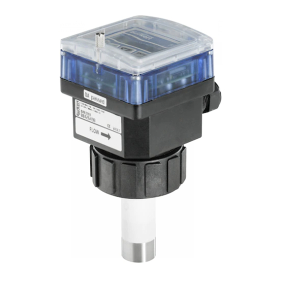
Insertion electromagnetic flowmeter
Hide thumbs
Also See for 8045:
- Instruction manual (144 pages) ,
- Quick start manual (98 pages) ,
- Operating instructions manual (74 pages)

Related Manuals for Burkert 8045


Summary of Contents for Burkert 8045
- Page 1 Type 8045 Insertion electromagnetic flowmeter Magnetisch-induktives Durchfluss-Messgerät, Insertion Débitmètre électromagnétique à insertion Quickstart English Deutsch Français...
- Page 2 We reserve the right to make technical changes without notice. Technische Änderungen vorbehalten. Sous réserve de modifications techniques. © Bürkert SAS, 2012 - 2019 Quickstart 1904/04_EU-ML 00563855 / Original FR...
-
Page 3: Table Of Contents
Type 8045 1. About the QuickstArt.................4 2. intended use ....................5 3. bAsic sAfety informAtion ...............5 4. GenerAl informAtion ................7 5. description of the rAtinG plAte ..........7 6. technicAl dAtA ...................8 7. instAllAtion And wirinG ..............13 8. Adjustment, commissioninG ................25 9. mAintenAnce And troubleshootinG ........32 10. pAckAGinG, trAnsport ..............32 11. storAGe ....................... 32 12. disposAl of the device ..............32... -
Page 4: About The Quickstart
▶ Failure to observe this warning can result in death or in serious 1.2. Definition of the word "device" injury. The word "device" used within this Quickstart refers to the insertion Warning electromagnetic flowmeter type 8045. warns against a potentially dangerous situation. ▶ Failure to observe this warning can result in serious injury or even death. English... -
Page 5: Intended Use
• the local safety regulations for which the operating company is respon- The insertion electromagnetic flowmeter type 8045 is intended sible including the staff in charge of installation and maintenance. exclusively to measure flow rate in liquids. - Page 6 Type 8045 Basicsafetyinformation notiCe the device may be damaged by the fluid in contact with. various dangerous situations ▶ Systematically check the chemical compatibility of the compo- To avoid injury take care: nent materials of the device and the fluids likely to come into ▶ not to use the device in explosive atmospheres.
-
Page 7: General Information
4.2. Warranty conditions The condition governing the legal warranty is the conforming use of the 8045 in observance of the operating conditions specified in this Quickstart. 4.3. information on the internet You can find the Operating Instructions and technical data sheets regarding the type 8045 at: www.burkert.com... -
Page 8: Technical Data
13. Serial number EN 61010-1 14. Order code degree of pollution Degree 2 according to UL/ EN 61010-1 15. Shows the flow direction Fig. 1 : Rating plate of the 8045 insertion electromagnetic protection class IP65 , if the device is wired and if the flowmeter (example) according to cable glands are tightened and the iec / en 60529 cover lid is screwed tight. - Page 9 Type 8045 Technicaldata 6.2. conformity to standards and 6.4. ul certification directives The devices with variable key PU01 or PU02 are UL-certified devices and comply also with the following standards: The applied standards, which verify conformity with the EU Direc- tives, can be found on the EU Type Examination Certificate and/or •...
- Page 10 S020 fitting used (exposed to the (DIN 1.4404) is made of. fluid) • 0...+80 °C • 8045 with flow sensor in Seal 8045 with a G2" nut: PVDF Earth ring of the Stainless steel 316L • –15...+110 °C •...
- Page 11 PP (PN10) PVC (PN10) PVC + PP PVDF (PN10) T (°C) PVC (PN10) A: range of use Fig. 2 : Fluid pressure / fluid temperature dependency for a 8045 PP (PN10) with PVDF flow sensor and a fitting S020 in metal, PVC, +20 +40 +60 +80 +100 +120 PVDF or PP T (°C) Except DN100 for measuring devices with a clamp connection A: range of use Fig. 3 : ...
- Page 12 Type 8045 Technicaldata 6.7. electrical data relay outputs (do2 and To use the relay outputs in a wet do3) location, observe the following operating voltage • 18...36 V DC, safety instruction. • filtered and regulated • operating • hysteresis (by default), config- • oscillation rate: ±5 % urable, normally open •...
-
Page 13: Installation And Wiring
Type 8045 Installationandwiring insTAllATion AnD WirinG Danger danger due to the operation of the relay outputs of a ul 7.1. safety instructions device in a wet location. ▶ If a UL device is used in a wet location: Danger - energize the relay outputs with an alternating voltage of max. risk of injury due to high pressure in the installation. 16 Vrms and 22.6 Vpeak. risk of injury due to electrical voltage. - or energize the relay outputs with a direct voltage of max. - Page 14 Type 8045 Installationandwiring Protect this device against electromagnetic interference, flow direction ultraviolet rays and, when installed outdoors, the effects of the climatic conditions. 7.2. recommandations for installing the 8045 on the pipe 50 x DN 5 x DN 40 x DN 5 x DN → Choose an S020 fitting appropriate to the velocity of the fluid With control valve Pipe with 2 elbows at 90°...
- Page 15 Type 8045 Installationandwiring - Preferably install the device at a 45° angle to the horizontal centre of - Prevent the formation of air bubbles in the pipe in the section the pipe to avoid having deposits on the electrodes and false meas- around the device (see Fig.
- Page 16 → Position the arrow on the side of the device in the direction of the flow: the totalizers will increment. Fig. 8 : Installation into the pipe of a 8045 with a G2'' nut → Insert the device (mark 1 Fig. 8) into the fitting. → Tighten the nut (mark 3, Fig. 8) by hand on the device.
- Page 17 ▶ If a UL device is used in a wet location: - energize the relay outputs with an alternating voltage of max. 16 Vrms and 22.6 Vpeak. - or energize the relay outputs with a direct voltage of max. 35 V DC. flow direction Fig. 9 : Installation into the pipe of a 8045 with a clamp connection English...
- Page 18 Type 8045 Installationandwiring → Loosen the nuts of the cable glands. • Use a high quality electrical power supply (filtered and → Insert the cable through the nut then through the cable gland. regulated). → Make sure the earth cable coming from the housing and, on a •...
- Page 19 Type 8045 Installationandwiring Power cable shield Power cable shield Power supply Power supply 18-36VDC 18-36VDC Pipes in plastic Metal pipe Valve, pump,... (or earthing rings, If a direct earth connection is not possible, fit a 100 nF / 50 V not provided, inserted into the...
- Page 20 Type 8045 Installationandwiring 7.5.2. Terminal assignment and use of the terminal block 1 selectors Iout: 4...20 mA output (AO1) L+: V+ (positive voltage) L–: 0 V (power supply ground) PE: functional earth, wired in the factory (see Fig. 15) P+: positive transistor output (DO1) P–: negative transistor output (DO1)
- Page 21 Type 8045 Installationandwiring Use switch A to configure the wiring of the 4...20 mA cur- 1 2 3 4 5 6 rent output in sinking or sourcing mode. CURRENT CURRENT Earth cable coming from the housing. SINK SOURCE SINK SOURCE On a version with stainless steel flow sensor, a second cable is coming from the sensor.
- Page 22 Type 8045 Installationandwiring Position the switch to "SOURCE". 230 VAC 230 VAC 18-36 V DC 300 mA Fig. 16 : Wiring of the DO2 and DO3 relay outputs 4...20mA input at external device Power supply 7.5.4. Wiring the Ao1 current output For safety reasons, secure the cables using a non-con- ducting cable clamp. The 4...20 mA output can be wired in either sourcing or sinking...
- Page 23 Type 8045 Installationandwiring 7.5.5. Wiring the Do1 transistor output Position the switch to "SINK". 18-36 V DC 300 mA 5-36 VDC 18-36 V DC 300 mA Power supply 4...20mA input at external device Power supply Iout L+ L - PE P+ P- Supply PULSE 18...36 Vdc...
- Page 24 Type 8045 Installationandwiring 7.5.6. Wiring the Di1 digital input 18-36 V DC 300 mA 5-36 VDC 18-36 V DC Power supply Power supply CURRENT Iout L+ L - PE P+ P- SINK SOURCE Supply PULSE 18...36 Vdc Iout L+ L - PE P+ P- Supply...
-
Page 25: Adjustment, Commissioning
Type 8045 Adjustment,commissioning ADjusTmenT, commissioninG Power supply 18-36 V DC 8.1. safety instructions Warning risk of injury due to non-conforming operating. Non-conforming operating could lead to injuries and damage the CURRENT Iout L+ L - PE P+ P- device and its surroundings. SINK SOURCE Supply PULSE 18...36 Vdc ▶ The operators in charge of operating must have read and under- stood the contents of this quickstart. - Page 26 Type 8045 Adjustment,commissioning 8.2. operating levels of the device The device has two operating levels: the Process level and the Con- figuration level. Table 1 : Default settings of the device Function Default value Function Default value LANGUAGE English OUTPUT Hysteresis UNIT of the l/min. 3–= 0.000 flow rate UNIT of the litre 3+= 0.000...
- Page 27 Type 8045 Adjustment,commissioning Configuration level Process level 12.6 L/s > 2 s > 5 s ENTER 0..9 16.45 mA Parameters menu Test Menu Information menu 0..9 ENTER mEAs. OVF CAL AO1 LANGUAGE > 5 s UNit CALiB 0 CAL. FAiL 87654 L...
- Page 28 Type 8045 Adjustment,commissioning 8.3. Description of the navigation keys and the state leDs • Scrolling up the • Selecting the displayed parameter parameters • Confirming the settings • Incrementing the figure selected Status LED of relay DO3 (LED ON = contact closed) Device state LED: see fol- Status LED of relay DO2 (LED ON = lowing table.
- Page 29 Type 8045 Adjustment,commissioning 8.4. using the navigation keys you want to... press... move between parameters within a level or a menu. • to go to the next parameter. • to go to the previous parameter. 0..9 access the Parameters menu. ENTER simultaneously for 5 s, in the Process level access the Test menu.
- Page 30 Type 8045 Adjustment,commissioning 8.5. choosing the display language 8.6. entering the k-factor of the fitting used When the device is energized for the first time, the display language is English. The device determines the flow rate in the pipe using the fitting K-factor. LANGUAGE ENGLish The K-factor of the fitting used can be entered here.
- Page 31 Type 8045 Adjustment,commissioning K-FACtOR K=10.000 K=2.8500 → Enter the K-factor (value between 0,0001 and The display shows the K-factor of the fitting, may it have been entered or 9999,9) of the fitting used. determined by a teach-in procedure; → Confirm the displayed value.
-
Page 32: Maintenance And Troubleshooting
Type 8045 Maintenanceandtroubleshooting mAinTenAnce AnD 10. pAckAGinG, TrAnsporT TroubleshooTinG notiCe damage due to transport 9.1. safety instructions Transport may damage an insufficiently protected device. ▶ Transport the device in shock-resistant packaging and away Danger from humidity and dirt. ▶ Do not expose the device to temperatures that may exceed the risk of injury due to high pressure in the installation. - Page 34 www.burkert.com...
Need help?
Do you have a question about the 8045 and is the answer not in the manual?
Questions and answers