Table of Contents
Advertisement
Quick Links
INSTALLATION INSTRUCTIONS
™
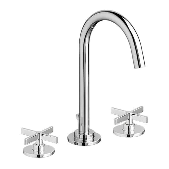
Percy
Widespread Lavatory Faucets
Cross Handle
Model D35105840
Cylinder Handle
Model D35105800
Thank you for selecting DXV by American Standard.
To ensure that your installation proceeds smoothly,
please read these instructions carefully
before you begin.
RECOMMENDED TOOLS AND MATERIALS
ROUGHING-IN DIMENSIONS:
In the United States:
In Canada:
- 1 -
In Mexico:
é
Advertisement
Table of Contents

Related Manuals for DXV Percy D35105840


Summary of Contents for DXV Percy D35105840
- Page 1 Widespread Lavatory Faucets Cross Handle Model D35105840 Cylinder Handle Model D35105800 Thank you for selecting DXV by American Standard. To ensure that your installation proceeds smoothly, please read these instructions carefully before you begin. RECOMMENDED TOOLS AND MATERIALS ROUGHING-IN DIMENSIONS:...
- Page 2 TEE ASSEMBLY SPOUT ASSEMBLY Turn off hot and cold water CAUTION supplies before beginning. slot SLOT INSTALL VALVE BODIES Note: VALVE BODY marked Hot (Red Dot) is installed in the left Mtg. hole, VALVE BODY marked Cold (Blue Dot) in the right when facing front of fitting.
- Page 3 INSTALL POP-UP DRAIN Fig. B. Fig. A. Fig. B. (1) Fig. A. DRAIN BODY (3) Fig. A. Fig. B. REMOVE MOUNTING WASHERS Fig. A. Fig. B. AND LOCKNUT REAR OF SINK (3) Fig. A. Fig. B. Note: SINK Fig. B. DRAIN HOLE ATTACH DRAIN FROM...
- Page 4 ATTACH CABLE CONNECTOR Fig. A. Fig. B. Fig. A. Fig. A. Fig. B. Note: " Fig. B. 1-1/4" O.D. (32mm) CHECK OPERATION OF POP-UP Note: MAKE WATER SUPPLY AND WASTE CONNECTIONS NOTE: FLEXIBLE SUPPLIES OR BULL-NOSE RISERS NOT INCLUDED AND MUST BE PURCHASED SEPARATELY. (1,1A) COUPLING 1/2"...
- Page 5 CONNECT DRAIN " 1-1/4" (32mm) O.D. TAILPIECE WASTE OUTLET TEST INSTALLED FITTING (3). (3). (4). CHECK DRAIN CONNECTIONS WASTE OUTLET TO CLEAN AERATOR COLD “P” TRAP - 5 -...
- Page 6 ® Speed Connect Drain Troubleshooting Guide If sink does not hold water even though Stopper is in the “down” position: If Stopper does not raise up fully or sink drains too slowly: If you need to remove the Stopper: If you would like the ability to remove your Stopper simply by lifting it out of the drain: “Unlocked”...
- Page 7 STOPPER INSTALLATION PROCEDURE The Stopper can be installed two ways, “Locked” Mode (Stopper cannot be removed) or “Unlock” Mode (Stopper is removable). Locked Mode: Fig. G. Fig. G. “Locked” rear Fig. G. Fig. J. LOOP TOWARD REAR OF SINK Fig. K. DRAIN Locked Mode (Vandal Proof)
- Page 8 ™ Percy Widespread Lavatory Faucets MODEL NUMBERS Cross Handle D35105840 Cylinder Handle D35105800 M964630-YYY0A M964629-YYY0A M964751-0070A M964752-YYY0A M964712-0070A M952430-0070A H960295.191 H960136.191 H960279.191 H960742.191 M953006-0070A H960104.191 874214.XXX H960741.191 - 8 -...
Need help?
Do you have a question about the Percy D35105840 and is the answer not in the manual?
Questions and answers