Table of Contents
Advertisement
Advertisement
Table of Contents

Subscribe to Our Youtube Channel
Related Manuals for Dormakaba Axessor CIT


Summary of Contents for Dormakaba Axessor CIT
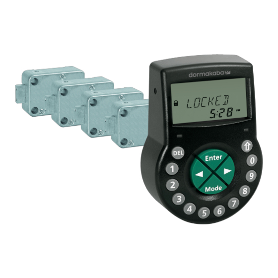
- Page 1 Electronic safe lock Axessor CIT Technical Manual V28 - 08/2019...
- Page 2 No part of this document may be reproduced or used in any form or by any means without prior written permis- sion of dormakaba Schweiz AG. All names and logos of third-party products and services are the property of their respective owners.
- Page 3 Technical Manual Version notes Version notes Document version Date Reason 2019-08 New functionalities included 2018-03 New functionalities included 2017-10 New document created Firmware version Date Reason 2019-08 New functionalities and optimizations: • Setting up Axessor CONNECT safe lock sys- tems with up to 10 locks, 2 input units and 1 eBox •...
- Page 4 The Master Code can override the Immediate Time Lock 2017-02 New functionalities: • Time Locking in OTM • Axessor CIT safe lock with time display • Harmonized bolt open times • OTM can override NRTD • Special function: User Code 41 configured as Audit and Battery Code •...
-
Page 5: Table Of Contents
Hazard category 10 Norms, standards and regulations 11 Certificates 12 System overview 13 System description 15 The Axessor CIT electronic safe locks 15 Product variants 15 6.2.1 Standalone variant with a single lock 15 6.2.2 Standalone variant with multiple locks 16 6.2.3... - Page 6 Table of Contents Technical Manual Installation 55 14.1 Drilling templates 55 14.2 Installing the input unit 57 14.3 Installing the lock 63 14.4 External connections on the lock 65 14.5 Installing the eBox 67 14.6 External connections on the eBox 67 14.7 eBox wiring diagram 69...
-
Page 7: Glossary
Technical Manual Glossary Glossary Terms Meaning A-CIT 28 Axessor CIT, version 28 A-IP 28 Axessor IP, version 28 A-IP N 28 Axessor IP NOT version 28 APHI Application Programming Hardware Interface AS274 AS274 server management software AS280-INSW AS280 Installation Software and Wibu dongle... - Page 8 Glossary Technical Manual Terms Meaning ONE SC4 bank One Shot Codes for Bank Mode One Time Code One Time Mode PRG-MOD Programming Mode PROCTIM cit Process Time CIT RMT-DIS Remote Disabling Single Mode TL-INT Time Locking Interruption TR-FCN 1 ... 3 Time-Related Function 1 ...
-
Page 9: About This Document
Technical Manual About this document 1 About this document 1.1 Purpose and objective This Technical Manual describes the Axessor CIT electronic safe locks with network capabili- ties. It gives information on: • The system and components • Technical data •... -
Page 10: Safety Information
Safety information Technical Manual 2 Safety information 2.1 Intended use The purpose of the electronic safe lock is to lock and unlock the mechanical blocking point of a safe, vault, data cabinet or ATM which is usually activated manually by bolt work. Do not modify the electronic safe lock since it will impair the security and safety of the unit. -
Page 11: Norms, Standards And Regulations
General Data Protection Regulation America Name Description UL Subject 2058 High-security electronic locks, type 1 - model Outline of investigation of high-security Axessor CIT, consisting of keypad P/N electronic locks 3310300311 and lock assembly P/N 3582705302 V28 - 08/2019 Electronic safe lock... -
Page 12: Certificates
Certificates Technical Manual 4 Certificates Europe Name Description ECB-S Electronic high-security lock, level B CNPP A2P Electronic high-security lock, level B Electronic safe lock V28 - 08/2019... -
Page 13: System Overview
Technical Manual System overview 5 System overview Input unit Housing MODE key Connecting cable for lock unit LEFT/RIGHT key Interface (USB) for PC connection NUMERIC keys 0...9 ENTER key DEL key INFO/ESC key Battery compartment Beeper V28 - 08/2019 Electronic safe lock... - Page 14 System overview Technical Manual Lock and optional external power supply Lock housing Warranty seal Inputs/outputs Type label Pin for cable tie Connection sockets X1 and X2 External power supply (optional), 6 VDC, 2 A Optional eBox and power supply Power supply, 12 VDC, 1 A RJ45 socket Connector Reset opening...
-
Page 15: System Description
6 System description 6.1 The Axessor CIT electronic safe locks The Axessor CIT with network capabilities are motorized deadbolt locks and latchbolt locks with standard dimensions and integrated terminals. It is possible to connect the safe locks to an alarm center. The locks comply with all relevant safety standards. -
Page 16: Standalone Variant With Multiple Locks
System description Technical Manual • Connecting cable The lock provides: • 2 inputs • 2 outputs A further option is to connect an external power supply (6V DC/500mA) to the connection sockets X1 or X2. Requirements: • Only use the original Axessor power supply, 6 VDC, 2 A. •... -
Page 17: Network Variant With A Single Lock And An Optional Ebox
Technical Manual System description • Connecting cables The locks provide: • 2 inputs • 2 outputs The maximum length of the Axessor bus is 30 meters. 6.2.3 Network variant with a single lock and an optional eBox The number of different components required depends on: •... -
Page 18: Network Variant With Multiple Locks And An Optional Ebox
System description Technical Manual Safe 1 Safe 2 Safe n Local Area Network (10/100BaseT Ethernet) Internet Other devices Router PC with Firewall AS 284-NETW Programming Software 6.2.4 Network variant with multiple locks and an optional eBox NOTICE Battery discharge and heating up Operating a safe lock system with 2 input units being powered with batteries will cause a bat- tery discharge due to potential equalization. - Page 19 Technical Manual System description The connection between AS284-USBW or AS284-NETW programming software and the lock- ing system will be established with lock -1- (master lock) either via network or USB interface. The established connection will be used from all slave locks. The locks are clearly identified and administered by their serial number and their system ad- dress.
-
Page 20: Software Applications
Software applications Technical Manual 7 Software applications The AS280 and AS284 software products were not evaluated by UL 2058 and are only for supplementary use. Do not use third party USB hubs. © AS280-INSW Installation Software for the Windows operating system is applied to switch between Bank Mode and OTM Mode (ICS, OTC, CIT or DM) as well as Mixed Mode. -
Page 21: Scope Of Application
Technical Manual Scope of application 8 Scope of application When using software products, personal data can be recorded and processed. The provision of art. 6 (1) lit b from EU 2016/679 General Data Protection Regulation (GDPR) shall be applicable if processing of personal data aims to the fulfillment of a contractual or pre-contractual obligation The electronic safe locks have the following functions for applications in the high security sec- tor:... -
Page 22: Technical Data
USB for data exchange with a Connection to a computer for the computer configuration with AS284-USBW or AS284-NETW programming soft- ware Axessor bus For connection of the input unit, dormakaba proprietary bus system lock, external power supply or eBox Electronic safe lock V28 - 08/2019... -
Page 23: Mechanical Components
Technical Manual Technical data Interface type Interface property Description Max. length is 30 meters 9.3 Mechanical components Lock Component property Dimensions 85 x 61 x 33 mm Weight 495 g Motor bolt Dead bolt or optionally a spring bolt Relocker Integrated lock relocker Cycle times Opening/closing: approximately 2 seconds... -
Page 24: Factory Settings
Factory settings Technical Manual 10 Factory settings It is possible to select the following display languages: • English • French • German • Dutch • Italian • Spanish • Hungarian • Polish • Portuguese • Turkish Function Factory setting Possible to change with Input unit AS284-USBW or AS284-NETW... - Page 25 Technical Manual Factory settings Function Factory setting Possible to change with Input unit AS284-USBW or AS284-NETW (optional) User Code 41 as Audit and Battery Code User Code 42 as activa- tion code (including Audit and Battery Code) User Codes 45 and 46 for the activation of the out- put impulse signal User code 47 as Time...
- Page 26 Factory settings Technical Manual Function Factory setting Possible to change with Input unit AS284-USBW or AS284-NETW (optional) Code denial: Temporary lockout of Manager Codes and user groups Temporary lockout of sin- gle users Duress Code Duress Code criterion +/- 1 (last digit) Time-Related Functions for up to 3 user groups,...
- Page 27 Technical Manual Factory settings Function Factory setting Possible to change with Input unit AS284-USBW or AS284-NETW (optional) Duress Time Delay in 1 min. Bank Mode (per user group) Time Delay in OTM 0 min. Duress Time Delay in 99 min. Time Delay and Duress Countdown Time Delay...
- Page 28 Factory settings Technical Manual Function Factory setting Possible to change with Input unit AS284-USBW or AS284-NETW (optional) Remote Disabling via software Input 1: One function optionally assignable: 1. Remote Disabling 2. Controlled Disabling 3. Remote Enabling 4. Cancelling NRTD Input 2: One function optionally assignable: 1.
-
Page 29: Functionality
Technical Manual Functionality 11 Functionality 11.1 Display elements of the input unit Menu TIME Beeper Menu PROG DEL key Menu DELAY NUMERIC keys 0 ... 9 Menu CODE LEFT key Menu MISC MODE key Symbol "lock open", "lock closed" RIGHT key Symbol "replace batteries"... -
Page 30: Immediate Time Lock
Functionality Technical Manual 11.3 Immediate Time Lock The Immediate Time Lock is a useful function to bridge the time period until a regular locking period of the electronic safe lock starts. When the lock is closed, it is not possible to open it for the configured time period The maximum time period is 144 hours. -
Page 31: Beep Signals
Technical Manual Functionality • Immediate Time Locking • Time Locking (Weekly and Holiday Locking Periods) • Penalty • Remote Disabling Reaching an endpoint of a Time-Related Function does not reset Partial Locking. The state of the function "Partial Locking" (activated or reset) does not depend on the start- ing or endpoint of a Time-Related Function. - Page 32 Functionality Technical Manual Locked -3- (Bank Mode) The lock -3- is mechanically closed. It is possible to connect up to 10 locks in a safe lock system. After 3 seconds the current time will be displayed instead of the lock position. Locked (Bank Mode) The lock is mechanically closed.
- Page 33 Technical Manual Functionality Weekly Time Locking (Bank Mode and OTM) The lock is in a weekly locking period. It is not possible to open the lock, unless it was configured that the "Master can bypass Time Lock". The current time is displayed. It is only possible to open the lock by entering a valid code once the set locking period has elapsed.
- Page 34 Functionality Technical Manual The lock is currently waiting for the Non-Return Time Delay (NRTD) to elapse. It is not possible to open the lock during that time, unless it was configured to override with OTM code. It is possible to use the INFO/ESC key to check the battery status and the last closed seal. It is possible to configure different time delays for the code groups.
- Page 35 Technical Manual Functionality Entering second code - Dual Mode activated (Bank Mode) If the Dual Mode is activated, 2 codes must be entered to open the lock. The message shown on the display prompts the user to enter a second code. Master Code and Courier Code override the Dual Mode in Bank Mode.
- Page 36 Functionality Technical Manual It is possible to deny codes with a superior code. These codes are declared invalid for a certain time period until these codes are permitted again. When identifying with a denied code, the status message DENIED will be displayed. The selected function will not be executed, the lock condition remains unchanged.
-
Page 37: Access Codes
Technical Manual Functionality Active input unit An input unit with asterisk indicates an active device with version number 28. Passive input unit An input unit without asterisk indicates a passive device with version number 28. Active eBox An active eBox with version number 11. Passive eBox A passive eBox with version number 11. -
Page 38: Code Types
Functionality Technical Manual Code type Possible person in charge Description 4 Manager Codes (8 dig- Head cashier, shift man- It is possible to set the Manager its) ager Codes "to cannot open" with AS284-USB or AS284-NETW pro- gramming software. 36 User Codes (8 digits) Cashier, sales assistant There are 4 user groups with 9 users each assigned to a respective... - Page 39 Technical Manual Functionality Master Code 0 0 x x x x x x Manager 1 Manager 2 Manager 3 Manager 4 1 0 x x x x x x 2 0 x x x x x x 3 0 x x x x x x 4 0 x x x x x x User 11 User 21...
- Page 40 Functionality Technical Manual Time Lock even during an activated Immediate Time Locking period. "Can override the re- The Master Code is en- This prevents a com- mote disabled signal tered. plete lock-out. or remote disabled The Master Code is able state"...
- Page 41 Technical Manual Functionality 11.7.2.3 User Codes with special functions Keep in mind that incomplete and improper configuration of the special functions "Lock dis- abling" (User Code 48) and "Lock Enabling" (User Code 49) causes a lockout. It is not possible to open the secure storage unit via the input unit any longer. The bigger the secure storage unit (e.g.
- Page 42 Functionality Technical Manual User Code Description Result User Codes 45 and It is possible to define User When entering either User Code 45 Codes 45 and 46 as Impulse or 46 an impuls is generated on the Code via AS284-USBW or respective output.
- Page 43 Technical Manual Functionality 11.7.2.5.1 Duress Code in Bank Mode To activate a duress alarm in Bank Mode, the value 1 or a different value must be added to or deducted from the last digit of a code according to the configured duress criterion. It is possible to activate a duress alarm with all code types at any time.
-
Page 44: Access Rights
Access rights Technical Manual 12 Access rights Authorization is given to: • MA (Master) • Mx (Manager 1, 2, 3 and 4) • U (User) • C (Courier) Menu Function Authorized codes (config- Description ured with input unit, ex fac- tory) TIME Setting the time (hours,... - Page 45 Technical Manual Access rights Menu Function Authorized codes (config- Description ured with input unit, ex fac- tory) PROG Configuring Time-Related User group 1 com- Functions for user group prises all users of 1, 2 or 3 group 1, 1 Manager of group 1 and the Defining a starting and Master.
- Page 46 Access rights Technical Manual Menu Function Authorized codes (config- Description ured with input unit, ex fac- tory) MISC Activating or deactivating a Non Return Time Delay for OTC NRTD cit (off/on) DELAY Configuring a Non Return Time Delay HM NRTD HM (hours, min- utes) MISC Activating or deactivating...
- Page 47 Technical Manual Access rights Menu Function Authorized codes (config- Description ured with input unit, ex fac- tory) CODE Changing the Master It is not possible to Code delete the Master Code. CHANGE ? (no/yes) The Master Code Setting and confirming starts with '00'.
- Page 48 Access rights Technical Manual Menu Function Authorized codes (config- Description ured with input unit, ex fac- tory) CODE Setting Courier Code The Courier Code starts with '90'. Setting and confirming the Courier Code (8 dig- its) (8 digits) CODE Changing Courier Code CHANGE ? (no/yes) Setting and confirming the Courier Code (8 dig-...
- Page 49 Technical Manual Access rights Menu Function Authorized codes (config- Description ured with input unit, ex fac- tory) MISC Activating or deactivating When a language is the Language Info set to "on", the re- spective language LANG info (each of the 10 will be displayed in languages is off/on) the Info Menu.
- Page 50 Access rights Technical Manual Menu Function Authorized codes (config- Description ured with input unit, ex fac- tory) MISC Activating or deactivating The Manager 4 is Code Denial Bank Mode only able to activate or deactivate user GROUP 4 (off/on) group 4. When Code Denial is set to "on", the codes of user group...
- Page 51 Technical Manual Access rights Menu Function Authorized codes (config- Description ured with input unit, ex fac- tory) Activating the lock in The Master Code AS280-INSW for IP or must be entered in AS280-INSW to ac- tivate the lock for IP or OTM.
- Page 52 Access rights Technical Manual Menu Function Authorized codes (set in Description AS284-USBW or AS284- NETW programming soft- ware) Resetting the battery It is possible to reset message "BAT-CMP the battery message open" when entering 1 of the following User Codes: User Code 41 set as Audit Code and Bat- tery Code...
- Page 53 Technical Manual Access rights Menu Function Authorized codes (set in Description AS284-USBW or AS284- NETW programming soft- ware) Use AS284-USBW or User Codes 48 and AS284-NETW to define 49 must be defined up to 2 outputs of the together when both lock or 2 outputs of the codes are configured eBox.
-
Page 54: Unpacking And Checking Delivery
Unpacking and checking delivery Technical Manual 13 Unpacking and checking delivery 13.1 Checks before installation Requirements: • Unpack the delivery. • Make sure that the content is complete. Make sure that the delivery includes: • Input unit • Lock • Connecting cable •... -
Page 55: Installation
Technical Manual Installation 14 Installation NOTICE Lockout of secure storage units Closing the door of a secure storage unit while lock installation is not fully completed, will cause a lockout of secure storage units. • Do not close the door of a secure storage unit until all installation steps are successfully completed. - Page 56 Installation Technical Manual Lock template 17.9 25.2 17.9 1 2 3 4 5 6 7 8 3 x Ø5 41.3 Electronic safe lock V28 - 08/2019...
-
Page 57: Installing The Input Unit
Technical Manual Installation eBox template (optional unit) 14.2 Installing the input unit NOTICE Improper installation of the input unit Changing the installation sequence will cause damage to the input unit • Do not skip installation steps. • Follow the described installation sequence. As a requirement of EN 1300 the input unit must be installed onto the safe. - Page 58 Installation Technical Manual 4 x M4 Installing the base plate If the lock is installed directly behind the spindle hole and no other measure was chosen, a drill protection plate is required for UL approved retrofit installation. Fastening screws must be secured against loosening, e.g. by using threadlocking adhesive such as Loctite 243 (medium strength, blue).
- Page 59 Technical Manual Installation Install M4 threads into the fixation holes. 8. Remove the 3 screws from the bottom of the cover (1 installed in the battery compart- ment, 2 installed in the housing). 9. Remove the cover from the base plate. 10.
- Page 60 Installation Technical Manual NOTICE Excessive mechanical stress on cables Excessive mechanical stress on cables will cause damage to the insulation and conductor. • Keep cables away from moving parts. • Do not squeeze cables. • Do not fold cables. • Do not route cables along sharp edges.
- Page 61 Technical Manual Installation Carefully route the battery cable through the strain relief guides of the battery compart- ment and the base plate. Place the cover on top of the base plate in an angle >90°. Plug the battery cable into the 2-pole connector terminal and the connecting cable into the 6-pole connector terminal.
- Page 62 Installation Technical Manual Installing the cover Engage the cover in the notch on top of base plate. Slowly hinge down the cover onto the base plate while carefully routing the connecting cable to the lock chamber. Leave a spare loop. Make sure that the cables will not be squeezed.
-
Page 63: Installing The Lock
Technical Manual Installation 9. Make sure that the battery compartment is freemoving. 10. Carefully place the battery compartment in the right position. 11. Remove it again. 12. Do not put the batteries into the battery compartment. 13. Do not install the screw for the battery compartment yet. 14.3 Installing the lock Do neither remove nor damage the warranty seal. - Page 64 Installation Technical Manual Remove the burrs. Install M6 threads into the fixation holes. 5. Install the lock with the three M6x10 screws (it is also possible to use similar inch screws). 6. Make sure that the screw heads rest on the base of the shouldered fixation hole. Make sure to keep the space underneath the lock free for a re-closable system or a con- necting cable.
-
Page 65: External Connections On The Lock
Technical Manual Installation max. 1000N max. 5N Connecting the connecting cable X1, X2 Make sure that the connector is in the correct position. Carefully plug the connecting cable into 1 of the lock sockets X1 or X2. Tighten the connecting cable with the cable tie and carefully attach excess cable. 14.4 External connections on the lock The configuration of input 2 and the corresponding terminals 7 and 8 is realized via AS284- USB or AS284-NETW programming software. - Page 66 Installation Technical Manual When a micro switch is connected to input 2 and the closed micro switch indicates the status "door open", both checkboxes "Invert input (open contact to trigger)" and "door contact" must be selected in AS284-USBW or AS284-NETW programming software for a smooth op- eration.
-
Page 67: Installing The Ebox
Technical Manual Installation 1 2 3 4 5 6 7 8 Sockets Description Remarks X1, X2 Connection for input unit or eBox or Use the enclosed connecting cable. connection for power supply Only use the original Axessor power supply. 14.5 Installing the eBox As a requirement of EN 1300 the eBox must be installed inside the safe. - Page 68 Installation Technical Manual It is possible to assign functions of inputs and outputs via AS284-USBW or AS284-NETW pro- gramming software. 7 mm Terminal Description Unit 18/20 Power supply 9 ... 26VDC / 700 ... 200mA Output 3 Contact properties Factory setting: not assigned Switching voltage: Output 4 24VAC...
-
Page 69: Ebox Wiring Diagram
Technical Manual Installation X3 or X4 Connection to lock (it is only possible Use the enclosed connecting cable. to connect 1 lock to an eBox). It does not matter if X3 or X4 is used. RJ45 Connection to a LAN 10/100 Base T Ethernet Min. - Page 70 Installation Technical Manual Connect the connecting cable from terminal X2 of the first lock to terminal X1 of the sec- ond lock. Repeat the step before for the remaining locks. Connecting locks and optional eBox Connect the connecting cable from terminal X2 of the last lock to terminal X3 of the eBox. Connect the power supply to the eBox via the 20-pin plug.
-
Page 71: Hot Plugging
Technical Manual Installation The lock with the lowest serial number becomes the master lock, see Troubleshooting for iden- tification of serial numbers. The display shows LOCKED and the number of the lock position. The master lock is lock -1-. The slave locks have successive numbers from lock -2- to lock -10-. The assignment of the lock positions is random. -
Page 72: Wiring Options
Installation Technical Manual 8. Tighten the battery compartment with hexagon countersunk screws. Connecting the slave locks Connect the connecting cable from terminal X2 of lock -1- to terminal X1 of lock -2- . Repeat the step before for the remaining slave locks. ð... -
Page 73: Wiring Check Of The Lock
(bus system test). • If another error message appears, see Troubleshooting. 14.10 Wiring check of the eBox After finishing the installation, the Axessor CIT electronic safe lock is commissioned: • Conduct wiring check. • After an initialization period if the eBox is connected, the LED blinks twice green every 2 seconds. -
Page 74: Configuration
Configuration Technical Manual 15 Configuration 15.1 Programming Mode The Programming Mode changes factory set parameters, settings, codes and other functions. It depends on the programming level which codes are required. 15.1.1 Menu overview of the master lock The range of functions of the slave locks differs from the functions of the master lock. The functions LOCK INFO and FREEZE do not exist. -
Page 75: Accessing The Programming Mode
Technical Manual Configuration Symbol Menu Function Submenu PROG configuring locking periods IMM-TL WEEKLY HOLIDAY TL-INT TR-FNC 1 TR-FNC 2 TR-FNC 3 DELAY configuring time delay DELAY 1 DELAY 2 DELAY 3 DELAY 4 CNF WIN NRTD HM D-ALARM DUAL bank BLT OPN bank BLT OPN cit PROCTIM cit... -
Page 76: Changing And Saving Settings
Configuration Technical Manual Enter a code, for example 00023054 by using the NUMERIC keys. Confirm the code with the ENTER key. ð Now the lock is in Programming Mode. ð The main menu is displayed. ð The content of the main menu depends on the entered code. 15.1.3 Changing and saving settings It is possible to interrupt the modification dialog at any time without saving. - Page 77 Technical Manual Configuration ð The currently set time will be displayed. Use the LEFT or RIGHT key to select the current hour and enter a new time. Press the ENTER key to confirm. 5. Use the LEFT or RIGHT arrow key to adjust the minutes. 6.
-
Page 78: Menu Prog
Configuration Technical Manual ð The currently set time format will be displayed. Select either ON or OFF by pressing the LEFT or RIGHT arrow key Select "YES" in the "SAVE?" dialog by using the LEFT or RIGHT arrow key. 5. Press the ENTER key. 15.1.5.4 Setting DST Authorization: Master code... - Page 79 Technical Manual Configuration Use the LEFT or RIGHT arrow key to set the duration of time in hours and minutes to de- fine the locking period of the Immediate Time Lock. Select "YES" in the "SURE?" dialog by using the LEFT or RIGHT arrow key. 5.
- Page 80 Configuration Technical Manual 15.1.6.2.2 Changing an existing Weekly Locking Period It must be possible to open the lock between 2 Weekly Locking Periods. Weekly Locking Periods are saved in a chronological order, starting with Monday. It is possible to configure the Time Lock for OTM codes via AS284-USBW or AS284-NETW programming software.
- Page 81 Technical Manual Configuration Press the ENTER key. ð The count will be displayed. Press the ENTER key to define a new time period. Use the LEFT or RIGHT arrow key to set the month, day and year for the starting point of the Holiday Locking Period.
- Page 82 Configuration Technical Manual 15.1.6.4.1 Adding a Time Locking Interruption The duration of a Time Locking Interruption is limited to 144 hours. If the maximum of 8 defined Time Locking Interruptions is reached, no further entries are pos- sible. The display does not react any more. Select the submenu TL-INT.
- Page 83 Technical Manual Configuration Press the DEL key. 5. Select "YES" in the "CLEAR?" dialog by using the LEFT or RIGHT arrow key. 6. Press the ENTER key to confirm the setting. 15.1.6.5 Configuring Time-Related Functions It is possible to define up to 3 Time-Related Functions. Each Time-Related Function supports user group 1, 2 and 3.
- Page 84 Configuration Technical Manual 5. Press the ENTER key to confirm the setting. 6. Repeat these steps to set the minutes. Use the LEFT or RIGHT arrow key to set the hour for the endpoint of the Time-Related Function. 8. Press the ENTER key to confirm the setting. 9.
-
Page 85: Menu Delay
Technical Manual Configuration 19. If the Time-Related Function is not to be used for all days of a week, switch WEEKLY to "ON" by using the LEFT or RIGHT arrow key. 20. Press the ENTER key to confirm the setting. 21. - Page 86 Configuration Technical Manual Time Delays Valid for Time Delay 1 Master Manager 1 Users 11 ... 19 Time Delay 2 Manager 2 Users 21 ... 29 Time Delay 3 Manager 3 Users 31 ... 39 Time Delay 4 Manager 4 Users 41 ...
- Page 87 Technical Manual Configuration If Manager Codes were defined via AS284-USBW or AS284-NETW programming software as "Manager can change Confirmation Window", it is possible to change this setting with Man- ager Codes. Ex factory the Confirmation Window is set to 5 minutes. The minimum value is 1 minute.
- Page 88 Configuration Technical Manual 5. Select "YES" in the "SAVE?" dialog by using the LEFT or RIGHT arrow key. 6. Press the ENTER key to confirm the setting. 15.1.7.4 Configuring the Beeper Time Delay for Door Opening Alarm Submenu D-ALARM Authorization: Master Code Factory setting for the Beeper Time Delay for Door Opening Alarm is OFF.
- Page 89 Technical Manual Configuration 15.1.7.6 Configuring Bolt Open Time in Bank Mode Submenu BLT OPN bank Authorization: Master Code Ex factory the Bolt Open Time in Bank Mode is set to 6 seconds. When the lock is opened in Bank Mode, it will close automatically when the Bolt Open Time has elapsed.
- Page 90 Configuration Technical Manual 15.1.7.8 Setting Time Delay in OTM Submenu DELAY cit Authorization: Master Code or Manager Code Ex factory the Time Delay in OTM is set to 0 minutes. It is only possible to define minutes for the Time Delay. It is not possible to define seconds.
-
Page 91: Menu Code
Technical Manual Configuration Use the LEFT or RIGHT arrow key to set the desired Opening Time Delay (setting from 00:00 to 99:00 minutes). Press ENTER key. 5. Select "YES" in the "SAVE?" dialog by using the LEFT or RIGHT arrow key. 6. - Page 92 Configuration Technical Manual CONFIRM will be displayed shortly to ask the user to enter the same code to confirm the setting. 8. USE the NUMERIC keys to enter the same code again. 9. Press the ENTER key to confirm the setting. 15.1.8.3 Setting Manager Codes Submenu MANAGER...
- Page 93 Technical Manual Configuration 5. Use the NUMERIC keys to enter a new code. 6. Press the ENTER key to confirm the setting. ð "CONFIRM" will be displayed shortly to ask the user to enter the same code again. Use the NUMERIC keys to enter the same code. 8.
- Page 94 Configuration Technical Manual Select the menu CODE. Press the ENTER key. Use the LEFT or RIGHT arrow key to select the code type (for example "user") to be changed. Press the ENTER key. 5. Use the LEFT or RIGHT arrow key to select the code (for example "User Code 11") to be changed.
-
Page 95: Menu Misc
Technical Manual Configuration Press ENTER key. ð All data is reset to factory settings. 15.1.9 Menu MISC 15.1.9.1 Setting the Display Language By default the display language is English. It is possible to set the display language either with the input unit or via AS284-USB or AS284- NETW programming software. - Page 96 Configuration Technical Manual ð The Device Manager displays the number of all connected devices of the safe lock sys- tem. Press the Right arrow key to select the desired device. ð The selected devices will be displayed. ð Up to 10 connected slave locks will be displayed. Press the ENTER key to confirm the setting.
- Page 97 Technical Manual Configuration Press the ENTER key. ð The Device Manager displays the number of all connected devices of the safe lock sys- tem. Press the Right arrow key to select the desired device. ð The selected device will be displayed. Press the ENTER key.
- Page 98 Configuration Technical Manual Press the Right arrow key to select the desired device. ð The selected device will be displayed. Press the ENTER key. ð The safe lock type and the version number will be displayed. 5. Press the Right arrow key. ð...
- Page 99 Technical Manual Configuration 6. Press the ENTER key to confirm the setting. 15.1.9.4 Activating or deactivating Open Beeper The Open Beeper function is used to notify the user if for example a safe door is open or the bolt work is unlocked. 10 short beep signals sound every 20 seconds.
- Page 100 Configuration Technical Manual ð The message is displayed if the beeper is activated or deactivated. Select either ON or OFF by using the LEFT or RIGHT arrow key. Press the ENTER key to confirm the setting. 5. Select "YES" in the "SAVE?" dialog by using the LEFT or RIGHT arrow key. 6.
- Page 101 Technical Manual Configuration Press the ENTER key. Select either ON or OFF by using the LEFT or RIGHT arrow key. Press the ENTER key to move to the next language. 5. After having defined the "last" language, select "YES" in the "SAVE?" dialog by using the LEFT or RIGHT arrow key.
- Page 102 Configuration Technical Manual 5. Use the LEFT or RIGHT arrow key to activate (CDE DEN ON, access denied) or deactivate (CDE DEN OFF, access allowed) the Code Denial for the selected user group or manager. 6. Press the ENTER key to confirm the setting. Repeat steps 2 to 5 for the selected user groups and managers.
- Page 103 Technical Manual Configuration Select the submenu DUAL bank. Press the ENTER key. ð The currently set status of the Dual Mode will be displayed. By default Dual Mode is set to off. Use the LEFT or RIGHT arrow key to activate (DUAL ON) or deactivate (DUAL OFF) the Dual Mode.
- Page 104 Configuration Technical Manual Press the ENTER key. ð It is displayed when Time Lock Periods apply for OTM codes (ON) or do not apply (OFF). Select either ON or OFF by using the LEFT or RIGHT arrow key. Press the ENTER key to confirm the setting. 5.
- Page 105 Technical Manual Configuration Press the ENTER key. It is displayed when the current time is activated (ON) or deactivated (OFF). Select either ON or OFF by using the LEFT or RIGHT arrow key. 5. Press the ENTER key to confirm the setting. 6.
- Page 106 Configuration Technical Manual 15.1.9.19.2 Setting Freeze On To guarantee that the selected lock remains lock -1- (master lock), it is possible to set the function Freeze for a short moment to ON and then switch to Freeze OFF. The selected lock will be set as the master lock and even after a power interruption remains the master lock.
-
Page 107: Operation
Technical Manual Operation 16 Operation 16.1 Operating modes The electronic safe lock has 3 different operating modes: • Bank Mode only (factory setting) • One Time Mode only (OTC, ICS, DM (ICS and OTC), CIT) • Mixed Mode (Bank Mode and OTM ) Bank Mode Ex factory the electronic safe lock is set to be used as a conventional electronic combination lock. - Page 108 Operation Technical Manual ICS Mode ICS Mode ensures that a user is present on-site. The user identifies himself by entering a 4-digit ID on the lock. The input unit displays a 6-digit number. The number is transmitted to the dispatch center to generate an opening code. In contrast to OTC, the opening code is only valid for an adjustable time period.
-
Page 109: Code Entry
Technical Manual Operation Mixed Mode The Mixed Mode is set via AS280- INSW software. The Mixed Mode combines the advantages of Bank Mode and OTM. The change from OTM to Bank Mode is realized via the MODE key on the lock. If the lock is in OTM, the display shows "IDENTIF". -
Page 110: Lock Opening Procedure
Operation Technical Manual Enter at least the first 7 digits and continue adding any possible number combination. Enter the last digit of the code, for example 00123458921031 ... 256. Press the ENTER key. In Bank Mode codes are entered in 2 groups of 4 digits. The following procedure is carried out to open the lock or to enter the Programming Mode: If necessary, press any key to wake up the display. -
Page 111: Opening Procedure In Ics Mode
Technical Manual Operation 5. Press the ENTER key to confirm the code. 6. If an opening code with Time Delay was defined, the window for Opening Time Delay ap- pears and the timer starts counting the set Time Delay. ð The remaining time will be displayed. ð... -
Page 112: Opening Procedure In Otc Mode
Operation Technical Manual Press the ENTER key twice to confirm the ID. ð When the ENTER key is pressed only once, the duress alarm will be activated. ð The request code window appears indicating for 30 seconds the specific request code for ICS Mode, for example 654123. -
Page 113: Lock Closing Procedure
Technical Manual Operation ð When the ENTER key is pressed only once, the duress alarm will be activated Enter the received opening code from the dispatch center, for example 123456 by using the NUMERIC keys. 5. Press the ENTER key twice to confirm the code. ð... -
Page 114: Troubleshooting
Troubleshooting Technical Manual 17 Troubleshooting 17.1 Status messages on LCD If various causes lead to more than 1 error message REFUSED xx, the number of error mes- sages will be summed up. Example: REFUSED 12 = REFUSED 04 + REFUSED 08 REFUSED 50 = REFUSED 02 + REFUSED 16 + REFUSED 32 Status mes- Cause... - Page 115 Technical Manual Troubleshooting Status mes- Cause Solution Menu Submenu sage on LCD REFUSED 02 Unknown command: Call the vendor for technical The desired function is not support. available. The installed components are not compatible. REFUSED 04 Lock was closed during config- Make sure that the lock re- PROG Any submenu...
-
Page 116: Identification Of The Lowest Serial Number
Troubleshooting Technical Manual Status mes- Cause Solution Menu Submenu sage on LCD MOT FLT A motion fault occured during Reboot the input unit bolt movement. by removing the bat- teries. Wait for 1 hour before inserting new batter- ies. Make sure that the bolt moves smoothly. -
Page 117: Service
Technical Manual Service 18 Service 18.1 Cleaning NOTICE Damage to surface and interior of the input unit Cleaning the input unit with aggressive cleaning agents, solvents, abrasive agents or sprays, will cause damage to the surface and interior of the input unit. •... - Page 118 Service Technical Manual Deinstall the screw from the battery compartment on the bottom of the input unit. Carefully pull out the battery compartment until it comes to a stop. Replace the 3 old batteries by 3 new ones of the same type (3 alkaline AA batteries 1.5 V - LR6 or 3 lithium AA batteries 1.5 V - FR6).
-
Page 119: Maintenance
Technical Manual Maintenance 19 Maintenance 19.1 Replacing a defect lock 19.1.1 Removing the defect lock from the safe lock system It is assumed that e.g. lock -9- is defect. The lock must be removed from the bus. The functions Freeze and Lock info are set to OFF on lock -1- (the master lock). Authorization: Master Code Checking the defect lock Press the Right arrow key to navigate to lock -9-. -
Page 120: Adding A New Lock To The Safe Lock System
Maintenance Technical Manual ð The last 8 digits of the serial number of the defect lock will be displayed. 10. Press the Right arrow key. ð The customized 5-digit number will be displayed. By default, these are the last 5 digits of the serial number. - Page 121 Technical Manual Maintenance ð After a few seconds the new lock will be placed automatically to the vacant lock posi- tion -9-. The display shows a warning that the battery compartment of the newly added lock was opened. Enter a Battery Code to be able to operate the lock. 19.1.2.2 Adding a new lock with Freeze ON The function Freeze is set to ON and the Lock info is set to OFF on lock -1- (master lock).
-
Page 122: Removing The Error Message Of Lock Position -16
Maintenance Technical Manual Assigning the new lock to the vacant position Wait until the new lock will be placed automatically to the vacant lock position -9-. Press the LEFT or RIGHT arrow key several times. ð The new lock has been assigned to the vacant lock position, when the display shows a warning with battery compartment open. - Page 123 Technical Manual Maintenance ð The Device Manager displays the number of all connected devices of the safe lock sys- tem. Press the Right arrow key to select Lock -16-. ð Lock -16- will be displayed. 8. Press the ENTER key. ð...
-
Page 124: Disposal
Disposal Technical Manual 20 Disposal Do not dispose used batteries in domestic waste. Dispose batteries according to the local or national regulations. Packaging material must be disposed or recycled according to national or local regulations. At the end of the service life, the unit and its components must be returned to the manufac- turer or must be disposed at a collecting point. -
Page 125: Spare Parts And Accessories
Spare part Part number Axessor CIT input unit AXESSOR-CITIU Axessor CIT lock unit AXESSOR-CITLOCK Axessor CIT latchbolt lock unit without VdS certification AXESSOR-CITLLOCK Replacement WiBu dongle for AS284-W Administrator dongle AS284-AW Replacement dongle for AS284 installation dongle AS284-INSW AS284-W programming software with virtual dongle...
Need help?
Do you have a question about the Axessor CIT and is the answer not in the manual?
Questions and answers