Table of Contents
Advertisement
Quick Links
ORACODE SMART CONTROLLER INSTALLATION
1
1. SMART CONTROLLER POSITIONING
• Avoid placing the Smart Controller in close proximity
(< 5 feet / 2 m) to a WiFi device.
• Position the Smart Controller within 33 ft / 10 meters of
the lock.
• Avoid heavy obstruction between the Smart Controller and lock
(e.g., metallic or concrete wall or floor).
• Avoid placing the Smart Controller close to metallic objects (e.g.,
metallic table, refrigerator, filing cabinets, etc.).
2. SMART CONTROLLER CONNECTION
• Connect the Smart Controller to the Internet modem/router
using the Ethernet Cable.
• Boot up the Smart Controller by connecting the Power Adapter.
• The Smart Controller will perform any necessary updates during
the boot-up process, and the green LEDs on the top of the
Smart Controller will come on (no specific order). The boot-up
process can take from 30 seconds to a few minutes.
• Wait until all green LEDs are on. This confirms the Smart
Controller has successfully performed all necessary updates and
is ready to connect to the Oracode Server
Note: The ZigBee LED may not illuminate during the initial
installation. This is normal in most situations. Proceed with Wireless
Lock Activation.
2
WIRELESS LOCK ACTIVATION (PUT ON-LINE)
• Log on to your Oracode Live account (www.kabaecodewireless.com).
• Go to "Door Monitoring & Management" then to "Door Monitoring".
• Within the "Door Monitoring" module, select the door to be activated from the door list, and click the "Activate as
Wireless" button.
• Select the Time Zone where the controller and lock will be located. The Network Name will be populated
automatically, using the Door name as its basis. This can be edited if need be. Click "Save Changes".
• When you click the "Save Changes" button, the Activation number will be provided.
• Use this number to complete the Activation Process in the following steps 2.2 (for Oracode Live) or 2.3 (for
BeHome247).
1
PK3646_07_18
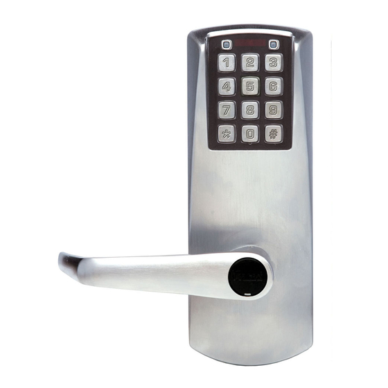
ORACODE 660i WIRELESS LOCK
ACTIVATION / PROGRAMMING
For 660i Wireless Locks with Standard Gateway
For 660i Wireless Lock with Smart Controller
Smart Controller (Top)
Smart Controller (Back)
USB
Ethernet
Power
Power
Ethernet
Adaptor
Cable
Advertisement
Table of Contents

Subscribe to Our Youtube Channel
Related Manuals for Dormakaba ORACODE 660i


Summary of Contents for Dormakaba ORACODE 660i
- Page 1 ORACODE 660i WIRELESS LOCK ACTIVATION / PROGRAMMING For 660i Wireless Locks with Standard Gateway For 660i Wireless Lock with Smart Controller ORACODE SMART CONTROLLER INSTALLATION Smart Controller (Top) 1. SMART CONTROLLER POSITIONING • Avoid placing the Smart Controller in close proximity (<...
- Page 2 Oracode 660i Wireless Lock Activation/Programming WIRELESS LOCK ACTIVATION (Continued) Smart Controller 2. ACTIVATION PROCESS (WITH ORACODE LIVE) (Bottom Label) • Once the Activation number is provided, a new field will be presented where the Smart Controller’s MAC address is to be entered.
- Page 3 Oracode 660i Wireless Lock Activation/Programming ORACODE SMART CONTROLLER DIAGNOSTICS 1. LOCK TO SMART CONTROLLER “CONNECTION” STATUS • Entering # # # 2 on the lock keypad triggers a “Lock to Smart Controller” status test. • A green LED and a high-pitched beep at the end of the test indicates the lock is connected to the Smart Controller.
- Page 4 Oracode 660i Wireless Lock Activation/Programming STANDARD ORACODE GATEWAY INSTALLATION Standard Oracode Gateway 1. GATEWAY POSITIONING • Avoid placing Gateways in close proximity (< 5 feet / 2 m) to a WiFi device. • Position the Gateway within 33 ft / 10 meters of the lock.
- Page 5 Oracode 660i Wireless Lock Activation/Programming STANDARD ORACODE GATEWAY DIAGNOSTICS 1. LOCK TO ORACODE GATEWAY “CONNECTION” STATUS • Entering # # # 2 on the lock keypad triggers a “Lock to Gateway” status test. • A green LED and a high-pitched beep at the end of the test indicates the lock is connected to the Gateway.
Need help?
Do you have a question about the ORACODE 660i and is the answer not in the manual?
Questions and answers