Table of Contents
Advertisement
Quick Links
Advertisement
Table of Contents

Subscribe to Our Youtube Channel
Related Manuals for Dormakaba YD30 Series


Summary of Contents for Dormakaba YD30 Series
- Page 1 YD30D Double Sideload Lock Installation & Operating Instructions...
-
Page 2: Table Of Contents
Table of Contents Document Information Contents and Purpose Target Group Safety and Compliance Safety Information Regulatory Compliance Information Product Information Product Description Package Contents Technical Data Product Dimensions Lock Dimensions Strike Dimensions Housing Dimensions (Available Separately) Dress Plate Dimensions (Available Separately) Fitting Tab Dimensions (Available Separately) Pre-Installation Assessment Mounting Assessment... -
Page 3: Document Information
Contents and Purpose This document describes installation, connection, operation, and maintenance of the lock SL30DBL. Read the document carefully and observe the instructions it contains. They contain important information for reliable installation and trouble-free operation. Target Group Target group of these instructions are: •... -
Page 4: Safety And Compliance
Safety and Compliance Safety Information WARNINGS • Live parts inside. • The handling and installation of this device is recommended for a professional. • Use of an unsuitable power supply unit may cause product failure or injury. • Do not remove the cover plates or face plate. •... -
Page 5: Regulatory Compliance Information
Compatibility Regulation 2016, and the Restriction of the Use of Certain Hazardous Substances in Electrical and Electronic Equipment Regulations 2012. CE and UKCA Declaration of Conformity is available at www.dormakaba.com. EN14846:2008 *Grade 0 for classification 4 ‘Suitability for use on fire/smoke doors’ applies only to the product when used as a primary latching device for a fire/smoke door. - Page 6 This product is regulated by the UL/CSA and bears UL/C-UL certification. Certifications: UL294, UL1034, ULC-S533-15 UL File Number: BP7604, R22400 UL Catagories: CVXY, ALVY, FWAX7, GWXT Line Security Level I Standby Power Level I UL294 Attack Level I Endurance Level IV Static Strength: 1,500 lbf (6,673N) UL1034 Dynamic Strength: 70 ft·lbf (95J)
-
Page 7: Product Information
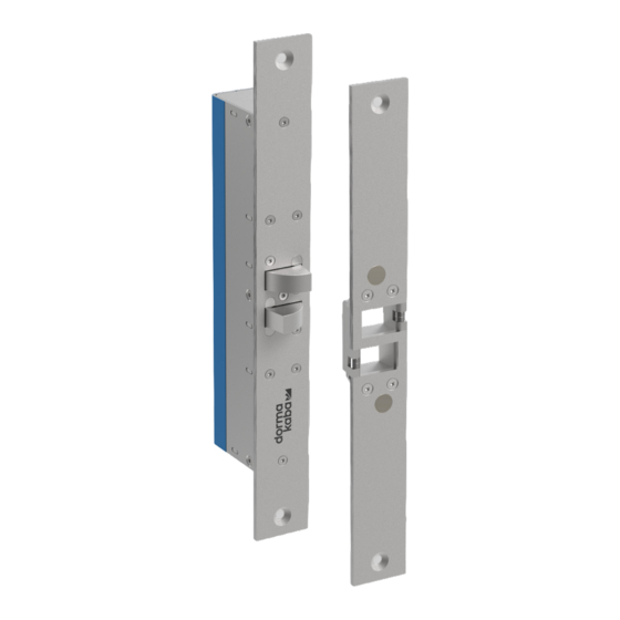
Product Description The SL30DBL is a motor driven low voltage electric lock designed to secure commercial and residential swing- through (180°) doors. The lock has been designed to address the two biggest issues in concealed electric locking today; The ability to ‘pull’ a door into alignment even if the door has not closed in a central position. 2. -
Page 8: Package Contents
Package Contents 1x Lock 1x Strike Plate 4x 10G self-tapping screws 1x 300mm 7-way wire loom... -
Page 9: Technical Data
Technical Data Materials Bolt Stainless Steel 17-4PH Lock / Strike Plate Stainless Steel 304 Mechanical Bolt Extension 13mm Door Gap max. 6mm (1/4 inch) Misalignment Correction max. 8mm (5/16 inch) Cycle Life 1,000,000 cycles Holding Force 10,000N (2,250 lbf) (factory tested only) Side Load Release 6,000N (1,350 lbf) (factory tested only) Locking Time... -
Page 10: Product Dimensions
Product Dimensions Lock Dimensions The dimensions shown are approximate and subject to change without prior notice. 183mm 7.205in 47mm 1.854in 255mm 10.039in 0.118in 30mm 1.181in 10mm 235mm 10mm 0.394in 9.252in 0.394in... -
Page 11: Strike Dimensions
Strike Dimensions The dimensions shown are approximate and subject to change without prior notice. 100mm 55mm 14mm 0.551in 3.937in 2.165in 255mm 10.039in 0.118in 30mm 1.181in 10mm 235mm 10mm 0.394in 9.252in 0.394in... -
Page 12: Housing Dimensions (Available Separately)
Housing Dimensions (Available Separately) The dimensions shown are approximate and subject to change without prior notice. 34mm 1.346in 220mm 20mm 8.661in 0.787in 56mm 259mm 2.189in 10.205in Dress Plate Dimensions (Available Separately) 260mm 58mm 10.236in 2.283in... -
Page 13: Fitting Tab Dimensions (Available Separately)
Fitting Tab Dimensions (Available Separately) The dimensions shown are approximate and subject to change without prior notice. 20mm 0.787in M5x0.8 Thread 38mm 24mm 1.476in 0.945in 0.157in... -
Page 14: Pre-Installation Assessment
Pre-Installation Assessment Mounting Assessment The first decision regarding installation is whether the SL30DBL will be mortised or surface mounted. Mortise installation ensures a discrete solution as the lock and strike plate can be embedded into the door leaf and frame, however in some instances this is not possible. Glass doors for example require surface mounting which is done with the aid of the SL30DBL housing and dress plate (available separately). -
Page 15: Wiring Assessment
Wiring Assessment Before installation begins, consideration must be made for where to run the wires and decide on what feedback is required from the lock. There are a total of seven available connections; three are compulsory power/control connections whilst the remaining four provide optional door and bolt position feedback. These optional connections can be integrated into access control or alarm systems to provide full monitoring. -
Page 16: Mounting
Mounting Mortise Installation (Solid Wood) Cutting the mortise Referring to the product dimension drawings, a mortise is cut into the door frame to fit the lock and a mortise is cut into the door leaf to fit the strike. Wooden doors and frames require full mortises with space made behind the lock body to accommodate the wire connections. -
Page 17: Mortise Installation (Metal Extrusion)
Mortise Installation (Metal Extrusion) Referring to the product dimension drawings, a mortise is cut into the door frame to fit the lock and a mortise is cut into the door leaf to fit the strike. Metal doors and frames, being hollow, often only require a single rectangle cut-out to accommodate the lock face plate or strike plate. -
Page 18: Surface Mounting Installation (Solid Wood)
Surface Mounting Installation (Solid Wood) Install two 10Gx1” self-tapping screws (included with housing) in the mounting surface, as per the product dimension drawings they should be 220mm apart, 20mm from the surface edge. An 8mm hole should be drilled through the housing wall at the position chosen by the installer for the wiring to enter. -
Page 19: Surface Mounting Installation (Glass)
Surface Mounting Installation (Glass) Fitting the housing Clean the glass surface with isopropyl alcohol and peel the protective layer from the double sided tape of the housing. Position the housing flush with the edge of the glass, and press down to adhere tape to surface. 2. -
Page 20: Wiring Guide
Wiring Guide The SL30DBL is supplied with a 7-way wire loom that plugs directly into the lock. The wires are colour coded as per table below, with the power and control wires being essential connections and the four monitor connections being optional. Wire Colour Meaning Description... -
Page 21: Operating Mode
Operating Mode Fail Safe Operation Assume the lock is installed, wired, and set to fail safe. The door is open and the positive supply voltage is applied to the BLUE wire. As the door closes the SL30DBL senses the door approaching and activates the bolt pin to pull the door into alignment. -
Page 22: Maintenance
Maintenance Maintenance and Cleaning The lock has been factory lubricated for life and is maintenance free. The use of other lubricants is not permitted and will void the warranty. This lock contains electromechanical and electronic components that are subject to wear and tear depending on use and on-site installation conditions. - Page 23 Notes...
- Page 24 Lodging Key Systems Systems Entrance Interior Glass Systems Systems Safe Service Locks DN 01004/002 10-2023 dormakaba USA dormakaba Canada 6161 E. 75th Street 7301 Decarie Blvd Indianapolis, IN 46250 Montreal QC H4P 2G7 T: 1 888 539 7226 dormakaba.us dormakaba.com...
Need help?
Do you have a question about the YD30 Series and is the answer not in the manual?
Questions and answers