Sign In
Upload
Download
Add to my manuals
Delete from my manuals
Share
URL of this page:
HTML Link:
Bookmark this page
Add
Manual will be automatically added to "My Manuals"
Print this page
×
Bookmark added
×
Added to my manuals
Manuals
Brands
Dormakaba Manuals
Locks
5715
Installation manuals
Dormakaba 5715 Installation Manuals
La gard basic series; gard series; electronic entry device
Hide thumbs
1
2
3
4
5
6
7
8
9
page
of
9
Go
/
9
Bookmarks
Advertisement
Quick Links
Download this manual
Document Number 762.128
Rev. G — 05 / 2018
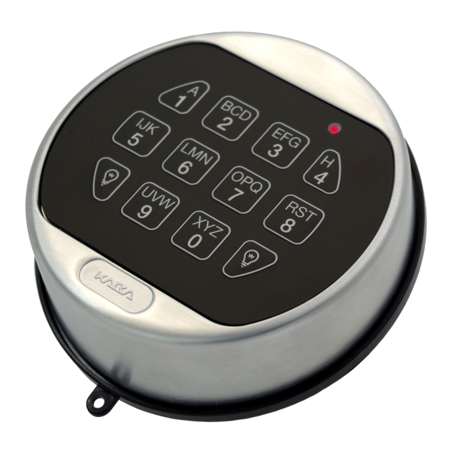
Installation Guide
Electronic
Entry Device
LA GARD Basic &
Gard Series
Table of
Contents
Previous
Page
Next
Page
1
2
3
4
5
Advertisement
Need help?
Do you have a question about the 5715 and is the answer not in the manual?
Ask a question
Questions and answers
Related Manuals for Dormakaba 5715
Intercom System Dormakaba LA GARD 5700 Series User Operating Instructions
Electronic entry device (2 pages)
Keypad Dormakaba LA GARD 5750-K User Operating Instructions
Electronic entry device (2 pages)
Locks Dormakaba AUDITCON 2 SERIES Installation Instructions
Round housing dead bolt (4 pages)
Locks dormakaba 3000 Installation Manuals
La gard basic series; gard series; electronic entry device (9 pages)
Locks Dormakaba 2725-K6 Technical Manual
C-lever compact (35 pages)
Locks dormakaba digital cylinder Technical Manual
Electronic locking cylinder (44 pages)
Locks dormakaba GL10 Operating Instructions Manual
Electronic gate lock (12 pages)
Locks dormakaba M Series User Manual
(44 pages)
Locks dormakaba Axessor Series Quick Reference Manual
(12 pages)
Locks dormakaba BEST Wi-Q 45HQ Installation Instructions Manual
Mortise locks (12 pages)
Locks Dormakaba La Gard Reset Box User Manual
(2 pages)
Locks Dormakaba LA GARD 700 Series User Manual
(44 pages)
Locks Dormakaba M1000 Series Installation Instructions
Mechanical mortise locks (4 pages)
Locks Dormakaba RCI DE8310 User Manual
Delayed egress v1.6 electromagnetic locks (2 pages)
Locks Dormakaba ILCO 79 Series Installation Manual
Locks with mechanical key override (2 pages)
Locks dormakaba ORACODE 660i Manual
Wireless lock activation / programming for 660i wireless locks with standard gateway (5 pages)
This manual is also suitable for:
3000
3035
5750-k
3125
5750
Print
Rename the bookmark
Delete bookmark?
Delete from my manuals?
Login
Sign In
OR
Sign in with Facebook
Sign in with Google
Upload manual
Upload from disk
Upload from URL


Need help?
Do you have a question about the 5715 and is the answer not in the manual?
Questions and answers