Table of Contents
Advertisement
Advertisement
Table of Contents

Related Manuals for Sartorius IF Series


Summary of Contents for Sartorius IF Series
- Page 1 Presented By Dallas Ft Worth Austin Houston NicolScales.com 800.225.8181 Contact Us Nicol Scales & Measurement is an ISO Accredited Calibration Company that has provided calibration, repair and sales of all types of weighing and measurement products since 1931.
- Page 2 Installation and Operating Instructions Sartorius IF.. Standard and IF...CE with T8 Lifting Mechanism Flat-bed Scale 98648-012-37 98648-012-37...
-
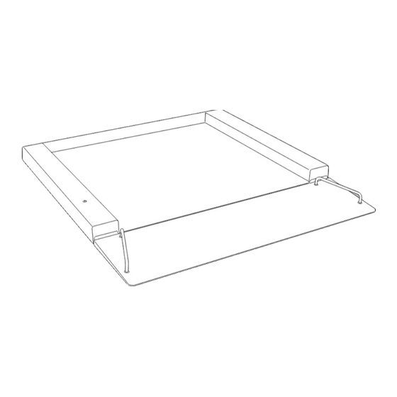
Page 3: General View Of The Equipment
General View of the Equipment General View of the Equipment 1 IF weighing platform 2 Pneumatic spring retainers 3 Base frame 1 Weighing platform 4 Right-hand downholder| Left-hand downholder 5 Right-hand stop bolt| Left-hand stop bolt 2 Handles|guide bars 6 Mounting aid 3 Level indicator 7 Carrier frame 4 Drive-on ramp... -
Page 4: Table Of Contents
Accessories (Options) .............. 14 turer’s warranty. Dimensions (Scale Drawings) ............ 14 – If the equipment housing is opened by anyone other than per- Declarations of Conformity ............ 15 sons authorized by Sartorius, this will negate its con f or m ity with regulations governing its use and result in forfeiture of all claims under the manufacturer’s warranty. The following symbols are used in these instructions: – Installation of the display and control unit/indicator must be § indicates required steps performed by a certified electrician who is familiar with the... -
Page 5: Installation Instructions
– The allowable operating temperature Note: Unpacking the Equipment range is -10°C to +40°C (+14°F to Connection of the scale to a display § Please read the enclosed operating +104°F). and control unit/indicator, installation, instructions carefully before putting the – If there is any indication that the configuration, and putting the equip- scale into operation. equipment does not function properly ment into operation must be performed § After unpacking the equipment, please (e.g., display remains blank, or no by a trained dealer or Sartorius service check it immediately for any visible display backlighting) due to damage representative. Details on additional damage. during transport, disconnect the equip- settings are contained in the Sartorius $ If you detect any damage, proceed as ment from power and notify your service manual. directed in under “Safety Inspection” nearest Sartorius Service Center; see in the chapter entitled “Care and also: “Safety Inspection” in the chapter – Unplug the power cord from the wall Maintenance.”... - Page 6 § Lift the scale evenly. Affixing Equipment Designation Labels to the IF...CE Equipment designation labels that correspond to configuration of the scale must be affixed to the equipment prior to initial verification. To do this, affix the labels to the display and con- § Move the scale to the place of instal- trol unit/indicator or, in special cases, to the plates provided. If lation. plates are required, they are included in the equipment supplied with the display and control unit/indicator. Fasten the plate to Warning: Danger of personal injury! the connecting cable between the IF...CE and the display and Do not stand or move beneath the control unit/indicator and affix the label to the plate. scale while it is suspended. Make sure to read and follow the Connecting the Flat-bed Scale to Power safety instructions. The flat-bed scale is powered over the cable that connects the display and controle unit/indicator. § Lower the scale evenly to the place of installation. $ The place of installation must be clean, level and able to withstand the weight of the scale and any load that will be placed on it. Eliminate any unevenness of the floor surface Unpacking the Equipment...
- Page 7 § Check the gap between the down- § Install the pneumatic springs holders (right and left) and the scale; (right and left) as shown in the it should be 2 mm. illustration. – U se a 2-mm thick spacing plate Tighten the bolts (size M10; wrench size: 17). – Measure the gap. $ Check this gap at regular intervals to make sure the 2-mm space is maintained. § Following installation, return the § Adjust the gap as needed. platform to the horizontal position. If necessary, loosen the bolts that § Turn the rear stop bolts (right and attach the downholder. Bolt size: M8; wrench size: 13. left). The bolts slide out of the side plate and release the platform. Danger of damage to the stop bolts! The stop bolts must be disengaged! § Before the scale platform can be § Grasp the platform by the handles raised to a vertical position, loosen and lower it to the horizontal the stop bolts on the right and left. position. Note: Danger of damage to the stop Two persons are required for...
- Page 8 § Remove the right and left mounting § Attach the two hand cranks to aids as follows: the two threaded fasteners at the Unscrew the four M8 bolts as shown front of the scale. § Turn the cranks clockwise to lower (wrench size: 13). the transport rollers. $ Repeat this procedure for the two rear rollers. Important: Make sure there is no load on the platform before you move it. § Hook the drive-on ramp onto the § The scale can now be moved into right and left retainers. the desired position. § If available, fasten the towing bar (optional) as shown. Transporting the IF (Option T7) § The scale can now be pulled into § Make sure there is no load on the the desired position. $ This procedure is useful, for exam- scale. § Remove the drive-on ramp from the ple, for cleaning the surface beneath front of the scale.
-
Page 9: Lift-Up Mechanism (Option T10)
Lift-up Mechanism (Option T10) § Align the transverse strut (3) with four screws M5 + 8 so that it is perpendicular to the left side plate (1) and right side plate (2), and screw the strut and side plates together. § Screw the left base plate (7) and the left side plate (1) together, and the right base plate (8) and right side plate (2) together, using screw M12 + 65 and nut M12. § Place the lift-up mechanism in an upright position on the instal- lation site and secure the base plates (7 and 8) to the floor with four heavy-duty dowels (fastening anchors M10 + 90). It must be checked in advance that the dowels supplied are suitable for the floor surface. § Guide the scale measurement cable through the left strut. Do not separate the scale platform and display device; otherwise the scales will no longer be calibrated for use in legal metrology. § Drive the sleeves (17) L = 42 mm into the left and right base plate (8). The measurement cable should be located Hülse M10+55 between the sleeve and the side plate. § Drive the fastening anchors in completely and screw together with nut M10. Important: Concrete that can withstand the load is required; otherwise the anchor will not remain stable. Important: Cut off the protruding end of the dowel. - Page 10 § Screw the four downholders (9) to the side plates (1 and 2) using M6 + 20. The platform and the downholders must be approx. 2 mm apart. § Check the gap using spacing plates (10). § Lift the platform up and secure. Fix the pneumatic springs § Secure the pneumatic springs (12) to the base plates (7 and 8) (12) to the side with screws M10 + 25 and flat nuts M10. plates (1 and 2) Note the installation position of the pneumatic springs: plunger using screws M10 + on the bottom, pressure pipe on the top. 65, nuts M10, and sleeves L = 16 mm. § Carefully position the scale platform so that the back load- bearing feet are in the fastening plates of the transverse strut and align.
- Page 11 § Screw the eye bolts to the left longitudinal strut from below § Mount the grips to the scale platform: using screws M6 + 20, and fix the measurement cable to the eye Drill holes on the front side and secure the grips using screws bolts with a cable clip. and nuts. § Press in the plastic impact cap (19) to protect the flooring. § Mount the drive-on ramp: Attach the drive-on ramp on the right and left side of the equipment. § When lifting up and down for the first time, ensure that the measurement cable is not damaged or squashed.
-
Page 12: Connecting The If.. Flat-Bed Scale
Connecting the IF.. Flat-bed Scale Connecting Cable: IF … to Display and Control Unit or Indicator 011 MP58 Cable, gray Cable, green V + (Supply voltage +) blue V – (Supply voltage -) black/brown blue Signal + (Output signal +) white green Signal – (Output signal -) red/pink gray Sense + (Sense line +) green white Sense –... - Page 13 The IF.. Weighing Platforms Example of model designation: R esolution, not verifiable: IF P 1500 RR -LCE 15,000 d = L, 30,000 d = I V erifiable: 3000 e = LCE, 2 +3000 e = NCE P = Weighing Dimensions Painted capacity in kg steel Load cells S = Stainless steel 1000 1500 3000 The IF.. Weighing Platforms Painted models: – Weighing capacities from 150 kg 600 + 600 to 3000 kg – 11 different sizes – 6 weighing capacities...
-
Page 14: Care And Maintenance
Cleaning Beneath the Load Plate (Option T8) based in Goettingen, Germany. Maintenance and repair work may be Important Note: The load plate must be locked into the vertical position performed only by authorized Sartorius service technicians who have or held in this position by a second person. access to the required maintenance manuals and have received the nec- Warning: Danger of personal injury! Make sure to observe all warnings essary training. and the safety precautions. All personnel must wear steel-toed boots ! The seals affixed to this equipment indicate that only authorized service while performing work that involves lifting or raising the load plate. technicians are allowed to open the equipment and perform mainte- nance work so that safe and trouble-free operation of the equipment is ensured and the warranty remains in effect. Storage and Shipping Conditions $ The packaging used for shipping your Sartorius equipment is optimally designed to prevent damage during transport. It is a good idea to save the box and all parts of the packaging for future storage or shipment of the equipment. Only the original packaging pro- vides the best protection for shipment. $ Allowable storage temperature: –20°C to +75°C (–4°F to +167°F) $ Allowable humidity during storage: max. 90% $ Please refer to the information under “Warnings and Safety § Use the foot switches on the § Use the handle to lift the front Precautions.” right and left and lower the of the load plate upwards. safety catch. Observe all warnings and safety... -
Page 15: Specifications
Specifications General Specifications for the IF-... Models Model IF.. Allowable ambient operating temperature °C –10 to +40 (+14°F to +104°F) IP rating IP65 (painted models) IP68 (stainless steel models) The cables supplied with the weighing platforms as standard equipment are 6 m in length. Capacities: Up to 3000 kg, with restrictions, when the load is distributed on the load plate. Accessories (Options) Order no. Additional drive-on ramps available on request Frame for pit installation available on request For affixing the weighing platform to the floor: Floor-mounting set YFP01I Columns can be manufactured to order on request. Dimensions Designation D (mm) 600 800 800 1,000 1,000 1,000 1,250 1,250 1,500 1,500 2,000... -
Page 16: Declarations Of Conformity
Declarations of Conformity The C marking may be affixed only 73/23/EEC “Electrical equipment “EC Verification” – to equipment that complies with the designed for use within certain voltage A Service Offered by Sartorius following Directives (below). Conformity limits” as amended by 93/68/EEC Our service technicians authorized to has been tested in conjunction with Applicable European Standards: perform the verification of your weigh- Sartorius equipment: ing instruments that are acceptable EN 60950 S afety of information for legal metrological verification can Council Directive 89/336/EEC... - Page 29 Sartorius Weighing Technology GmbH Weender Landstrasse 94–108 37075 Goettingen, Germany Phone +49.551.308.0 Fax +49.551.308.3289 www.sartorius-mechatronics.com Copyright by Sartorius, Goettingen, Germany. No part of this publication may be reprinted or translated in any form or by any means without the prior writ- ten permission of Sartorius. All rights reserved. The status of the information, s pecifications and illustrations in this manual is indicated by the date given below. Sartorius reserves the right to make changes to the technology, features, specifications and design of the equipment without notice. Status: March 2013, Sartorius Weighing Technology GmbH, Goettingen, Germany Printed in Germany on paper that has been bleached without any use of chlo- rine RS· KT Publication No.: WIF6002-e13037...
Need help?
Do you have a question about the IF Series and is the answer not in the manual?
Questions and answers