Advertisement
Quick Links
Lazy Sprocket Kit Instructions
Warranty:
BYOC, Inc. guarantees that your kit will be complete and that all parts and components
will arrive as described, functioning and free of defect. Soldering, clipping, cutting,
stripping, or using any of the components in any way voids this guarantee. BYOC, INC
guarantees that the instructions for your kit will be free of any majors errors that would
cause you to permanently damage any components in your kit, but does not guarantee
that the instructions will be free of typos or minor errors. BYOC, INC does not
warranty the completed pedal as a whole functioning unit, nor do we warranty any of the
individual parts once they have been used. If you have a component that is used, but feel
it was defective prior to you using it, we reserve the right to determine whether or not the
component was faulty upon arrival. Please direct all warranty issues to:
sales@buildyourownclone.com This would include any missing parts issues.
Return:
BYOC, Inc. accepts returns and exchanges on all products for any reason, as long as they
are unused. We do not accept partial kit returns. Returns and exchanges are for the full
purchase price less the cost of shipping and/or any promotional pricing. Return shipping
is the customer's responsibility. This responsibility not only includes the cost of
shipping, but accountability of deliver as well. Please contact
sales@buildyourownclone.com to receive a return authorization before mailing.
1
Advertisement

Subscribe to Our Youtube Channel
Related Manuals for BYOC Lazy Sprocket


Summary of Contents for BYOC Lazy Sprocket
- Page 1 This would include any missing parts issues. Return: BYOC, Inc. accepts returns and exchanges on all products for any reason, as long as they are unused. We do not accept partial kit returns. Returns and exchanges are for the full purchase price less the cost of shipping and/or any promotional pricing.
- Page 2 That being said, we will do our best to help you as much as we can. Our philosophy at BYOC is that we will help you only as much as you are willing to help yourself. We have a wonderful and friendly DIY discussion forum with an entire section devoted to the technical support and modifications of BYOC kits.
-
Page 3: Table Of Contents
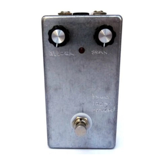
Parts Checklist…………………………..page 5 Populating the Circuit Board…………..page 6 - 13 Assembly………………………………..page 14 - 16 Wiring………………………………..page 17 - 20 Finish up………………………………..page 21 Operating Overview…………………….page 22 Schematic...........page 23... - Page 4 This is what your build should look like when it’s done. Your kit may include different color components; this is nothing to worry about as long as the values are correct.
-
Page 5: Parts Checklist
Parts Checklist for The Lazy Sprocket Kit Resistors: 1 - 390ohm (orange/white/black/black/brown) 1 - 470ohm (yellow/purple/black/black/brown) 3 - 1k (brown/black/black/brown/brown) 1 - 3.3k (orange/orang/black/brown/brown) 3 - 4.7k (yellow/purple/black/brown/brown) 3 - 10k (brown/black/black/red/brown) 3 - 22k (red/red/black/red/brown) 1 - 47k (yellow/purple/black/red/brown) -
Page 6: Populating The Circuit Board
Populating the Circuit Board Step 1: Add all the resistors. Resistors are not polarized, so they can face in either direction. - Page 7 Step 2: Add the diodes. The smaller 1N914 are highlighted in red. The larger zener is highlighted in yellow. Make sure the black stripe on each diode matches with the stripe on the layout.
- Page 8 Step 3: Add the IC socket. Match up the u-shaped notch in the socket with the notch on the layout. If the op amp that is supplied with your kit does not have a notch in it, there will be a small dot in one corner. This denotes pin #1.
- Page 9 Step 4: Add the trimpot. When you are finished with your build, adjusting this trimpot will be very important. When you set the trimpot, you want to have the attack knob turned full turn clockwise so that it should produce the slowest swell.
- Page 10 Step 5: Add the transistors. The 2N3904s are highlighted in red. The 2N5457 is highlighted in yellow. Make sure that the transistors' curved sides and flat sides match the layout. Using a SK30 JFET: If you wanted to use an SK30 JFET, the PCB has eyelets to accommodate this.
- Page 11 Step 6: Add the film caps. These are not polarized and can go in either direction.
- Page 12 Step 7: Add the electrolytic capacitors. These are polarized, meaning they have a positive and negative end. The positive end of the cap will have a longer lead and should go in the square solder pad.
- Page 13 Step 8: Add the battery snap. Thread the wires of the battery snap through the holes in the PCB before soldering as shown below.
-
Page 14: Assembly
Main PCB Assembly Step 1: Mount the AC adapter jack to the enclosure. Your kit may come with either an external thread or internal thread. Don’t get confused by this. They still function exactly the same. You just thread the external nut on the outside and the internal nut on the inside. - Page 15 Step 2: Flip the PCB over so that the bottom or solder side is up. Insert the four potentiometers, toggle switch and the LEDs into the bottom side of the PCB. DO NOT SOLDER ANYTHING YET!!! The LED will have one lead that is longer than the other. THIS WILL GO INTO THE SQUARE SOLDER HOLE.
- Page 16 Step 3: Hold the PCB in one hand so that the component side of the PCB is in the palm of your hand and the bottom side with the pots, toggle switch and LED is facing up. Now use your other hand to guide the predrilled enclosure onto the PCB assembly so that the pots, toggle switch and LED all go into their respective holes.
-
Page 17: Wiring
WIRING Step 6: Connect the TIP (negative) terminal of the DC adapter jack to the eyelet on the PCB labeled “-“. Connect the SLEEVE of the DC adapter jack to the eyelet on the PCB labeled “+” farthest to the right. Connect the battery disconnect terminal of the DC adapter jack to the second eyelet on the PCB labeled “+”... - Page 18 You will want to place the jacks into the enclosure so the sleeve terminal is facing the right like the picture above. Be sure to remember the lock washers so the jacks don’t spin on their own. Step 7: Install the footswitch. Orient the footswitch so that the flat sides of the solder lugs are like the diagram below.
- Page 19 FOOT SWITCH SOLDER LUG DESIGNATIONS Step 8: Insert the foot switch wires into their respective eyelets on the PCB. You can insert them into the top side and solder on the top side as well. The solder pads should be large enough (if you are using a soldering iron that isn’t too big) to allow you to do this without burning the PVC coating on the wires if you are careful.
- Page 20 Finished Wiring...
-
Page 21: Finish Up
Installing IC/Finish up Don't forget to add the knobs, put the cover on the enclosure, and apply the bumpers to the cover. -
Page 22: Operating Overview
Operating Overview ATTACK: Controls the speed of the effect. CCW is a slower swell effect; CW is a faster swell effect. SENSITIVITY: Controls the sensitivity of the effect, or how much signal must be present to trigger the swell effect. CCW requires a stronger signal to trigger the swell effect;... -
Page 23: Schematic
For High Resolution PDF visit: http://byocelectronics.com/lazysprocketschematic.pdf... - Page 24 PCB MAP Copyright 2018 Build Your Own Clone...
Need help?
Do you have a question about the Lazy Sprocket and is the answer not in the manual?
Questions and answers