Table of Contents
Advertisement
Quick Links
Build Your Own Clone
Overdrive 2 Kit Instructions
Warranty:
BYOC, LLC guarantees that your kit will be complete and that all parts and components
will arrive as described, functioning and free of defect. Soldering, clipping, cutting,
stripping, or using any of the components in any way voids this guarantee. BYOC, LLC
guarantees that the instructions for your kit will be free of any majors errors that would
cause you to permanently damage any components in your kit, but does not guarantee
that the instructions will be free of typos or minor errors. BYOC, LLC does not
warranty the completed pedal as a whole functioning unit nor do we warranty any of the
individual parts once they have been used. If you have a component that is used, but
feel it was defective prior to you using it, we reserve the right to determine whether or
not the component was faulty upon arrival. Please direct all warranty issues to:
sales@buildyourownclone.com This would include any missing parts issues.
Return:
BYOC, LLC accepts returns and exchanges on all products for any reason, as long as
they are unused. We do not accept partial kit returns. Returns and exchanges are for the
full purchase price less the cost of shipping and/or any promotional pricing. Return
shipping is the customers responsiblity. This responsibility not only includes the cost of
shipping, but accountability of deliver as well. Please contact
sales@buildyourownclone.com to receieve a return authorization before mailing.
Tech Support:
BYOC, LLC makes no promises or guarantees that you will sucessfully complete your kit
in a satisfactory mannor. Nor does BYOC, LLC promise or guarantee that you will
receive any technical support. Purchasing a product from BYOC, LLC does not entitle
you to any amount of technical support. BYOC, LLC does not promise or guarantee that
any technical support you may receive will be able to resolve any or all issues you may be
Advertisement
Table of Contents

Related Manuals for BYOC Overdrive 2


Summary of Contents for BYOC Overdrive 2
- Page 1 Overdrive 2 Kit Instructions Warranty: BYOC, LLC guarantees that your kit will be complete and that all parts and components will arrive as described, functioning and free of defect. Soldering, clipping, cutting, stripping, or using any of the components in any way voids this guarantee. BYOC, LLC...
- Page 2 That being said, we will do our best to help you as much as we can. Our philosophy at BYOC is that we will help you only as much as you are willing to help yourself. We have a wonderful and friendly DIY discussion forum with an entire section devoted to the technical support and modifications of BYOC kits.
-
Page 3: Table Of Contents
OVERDRIVE 2 KIT INSTRUCTION INDEX Parts Checklist ....page 4 - 6 Standard Spec Build Notes........page 7 - 8 MOSFET Spec Build Notes........page 9 - 11 Populating the Circuit Board ....page 12 - 22 Assembly ....page 23 - 25 Wiring the Footswitch & Jacks........page 26 - 28 Installing the ICs............page 29... -
Page 4: Parts Checklist
Parts Checklist for BYOC Overdrive 2 Resistors: 1 - 100ohm (brown/black/black/black/brown) 1 - 220ohm (red/red/black/black/brown) 1 - 470ohm (yellow/purple/black/black/brown) 3 - 1k (brown/black/black/brown/brown) 2 - 4.7k (yellow/purple/black/brown/brown) 8 - 10k (brown/black/black/red/brown) 1 - 100k (brown/black/black/orange/brown) 2 - 511k (green/brown/brown/orange/brown) 2 - 1M (brown/black/black/yellow/brown) or (brown/black/green/gold) - Page 5 1 - OP2134 1 - DIP 8 socket Hardware: 1 - drilled enclosure w/ 4 screws 1 - byoc OD2 circuit board 2 - SPDT PC mounted on-off-on toggle switch 2 - 3PDT footswitch 4 - knobs 1 - AC adaptor jack 1 - ¼...
- Page 6 MOSFET CONVERSION KIT Resistors: 1 - 4.7k (yellow/purple/black/brown/brown) 5 - 1M (brown/black/black/yellow/brown) Diodes: 6 - 1N914 or 1N4148 (small orange glass) Transistors: 5 - BS170 MOSFET (these go in backwards from the transistor labels on the PCB!) IC's: 1 - CA3260 Dual MOSFET OpAmp Potentiometer: 1 - B10k linear (tone knob)
-
Page 7: Standard Spec Build Notes
Standard Spec Build Notes If you are building your Overdrive 2 kit to standard tubescreamer specs, before you begin, you should be aware that there are several spaces on the PCB that should be left empty. There are 5 resistor spaces, 6 diode spaces, and 2 transistors spaces, highligted in the diagram above that should be left empty. -
Page 9: Mosfet Spec Build Notes
MOSFET Spec Build Notes If you are building your Overdrive 2 kit to MOSFET specs, before you begin, you should be aware that there are several spaces on the PCB that need to be left empty and several component values that need to be changed from what is labelled on the PCB. - Page 10 Change the 10k resistor highlighted in yellow to a 4.7k resistor. Change the 3 MPSA18 transistors highlighted in pink to BS170 MOSFETs. BS170 MOSFET transistors need to go in backwards. Just be aware of this for now. You will be reminded throughout the populating the PCB portion of the instructions as we come to each relevant component.
-
Page 12: Populating The Circuit Board
Populating the Circuit Board STEP 1: Add the diodes highlighted in red. Be sure to matched the end of the diode with the stripe to the layout on the PCB. The stripped end should go in the square solder pad. Only add the diodes highlighted in yellow if you are building to MOSFET specs. - Page 13 STEP 2: Add the resistors . Resistors are not polarized, so it does not matter which end goes in which solder pad. Standard Specs: Add all the resistors according to the values labelled on the PCB. Do not add any resistors to the spaces highlighted in green with blank values. However, one mod that people like to do is to increase the input impedence of the two transistor buffers.
- Page 14 d. Change the 100k to 1M and change the 10k to 4.7k in the spaces highlighted in yellow. Step3: Add the 8 pin socket. Line up the socket so that the u-shaped notch matches up with the end that has a notch on the layout. Only add the socket. DO NOT solder the actual chip to the PCB.
- Page 15 Step 4: Add the 3mm red clipping LEDs. The LEDs will have one lead that is longer than the other. The longer lead goes in the square solder pad hole. The shorter lead goes in the round solder pad hole. DO NOT add these if you plan on using the MOSFET clipping.
- Page 16 STEP 5: Add the film capacitors. These are not polarized so they can be inserted into the PCB in either direction.
- Page 17 Step 6: Add the tantalum capacitors. Tantalum caps are polarized. They will usually have symbol on their positive side. The positive side goes in the square solder pad hole. Use the .22uf (224) tantalum caps for stock tubescreamer specs. Your kit also comes with a pair of .15uf (154)tantalum caps.
- Page 18 Step 7: Add the ceramic disc cap. These are not polarized and can go into the PCB in either direction.
- Page 19 STEP 8: Add the internal trimpots. Many people get confused by these because the trimpot itself only has 3 legs, but the PCB has 5 holes. The PCB has 5 holes so that it can accomodate a variety of different trimpot brands and models. There should only be one way each trimpot will fit into the PCB without having to bend the legs.
- Page 20 STEP 9: Standard specs: Add the MPSA18 transistors to the spaces highligted in RED. Be sure to match up the flat side of the transistor with the flat side on the layout. The spaces highlighted in yellow are for MOSFET clipping transistors. If you are using the clipping LEDs, do not used the MOSFET clipping transistors.
- Page 21 STEP 10: Add the aluminum electrolytic capacitors. These are polarized. The positive end will have a longer lead and should go in the square solder pad. The negative end will have a shorter lead with a black strip running down the body of the capacitor.
- Page 22 Step 11: Add the battery snap. Thread the solder ends of the snap through the under side of the strain relief holes. Insert the stripped ends of the battery snap wires into the topside of their respective solder pads. Solder on the bottom side where highlited in blue. Remember the red wire goes in the hole and the black wire goes in the hole.
-
Page 23: Assembly
Assembly Step 1: Mount the DC adaptor jack to the enclosure. Step 2: Connect the TIP (negative) terminal of the DC adaptor jack to the eyelet on the PCB with 2 inches of hook up wire. Connect the SLEEVE of the DC adaptor jack to eyelet on the far right side of the PCB with 2 inches of hook up wire. - Page 24 Step 3: Flip the PCB over so that the bottom or solder side is up. Insert the B25k, A100k, B100K, and A500k potentiometers, the LED(long leads go in the square solder pad holes), and the two toggle switch into the bottom side of the PCB. DO NOT SOLDER!!!There are only two ways in which the toggle switch can fit into the PCB.
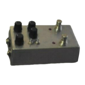
- Page 25 Step 4: Hold the PCB in one hand so that the component side of the PCB is in the palm of your hand and the bottom side with the pots, toggle switch and LED is facing up. Now use your other hand to guide the predrilled enclosure onto the PCB assembly so that the pots, toggle switch and LED all go into there respective holes.
-
Page 26: Wiring The Footswitch & Jacks
Wiring the footswitch, and jacks Step 1: Install the 1/4 jacks to the enclosure. Be sure to turn the OUT jack a 1/4 turn counter clockwise so that solder terminal for the tip does not short out against the enclosure. - Page 27 Step 2: · Cut 7 x 3/4 pieces of wire. Strip 1/8 off each end. These will be used to connect lugs/eyelets 1, 7, & 8 of the footswitch on the left and lugs/eyelets 1, 2, 7, & 8 of the footswitch on the right.
- Page 28 These will be used to connect lugs/eyelets 4 with the longer 1/2 stripped ends being used to jumper lugs 4 to 9 of both footswitches. · Cut 3 x 2 pieces of wire. Strip 1/4 off each end. These will be used to connect the tip and sleeve of the IN jack and the tip of the OUT jack to the PCB.
-
Page 29: Installing The Ics
Installing the IC... -
Page 30: Setting Up The Internal Trimpots
Adjusting the Trimpots All three trimpots affect the gain of the circuit, so all 3 trimpots are extremely interactive, especially the MIN and MAX trimmers. MIN trimmer: This trimmer will affect the amount of minimum distortion. Originally it was a 51k resistors, so setting this trimpot to exactly halfway will give you stock TS808 specs. - Page 31 Turing it up too much may cause squealing or self-oscillation. LOUDER trimmer: This trimmer affects the gain of the second half of the op amp. Originally it was a 1k resistor, so setting this trimpot to just shy of full turn counter clockwise will give you stock TS808 specs.
-
Page 32: More Modifications
More Modifications MOSFET or Standard Specs? Or a little of each? By most peoples' accounts, MOSFETs produce a smoother, more tube-like solid state distortion. This is a good thing, right? But MOSFETs are noisier than the usual components used in the TS circuit. So there is a give and take. The neat thing about this build is that it is not all or nothing or one or the other . - Page 33 experiment with. The MOSFET op amp cannot run at more than 9v. But the other op amps can run at 18v. · Output buffer highlighted in blue. The buffers are where most of the mosfet noise comes from. · Clipping section highlighted in red. Note that while you can use either the MOSFET transistors as clipping devices or the LEDs as clipping devices regardless of what specs you build the rest of the pedal to, you cannot have components on the PCB in both of these spaces at the same time.
- Page 34 produce more gain and volume. The drawback of this is that the boost will become dirtier as you increase the gain. This mod will work with both the standard and MOSFET build specs. Try a 100ohm or 220ohm resistor. You can even use a jumper for maximum gain.
- Page 35 highlighted in purple gets put into parallel with the cap highlighted in red with the toggle switch is to the right (position 3). Try a 220n or .22uf cap here. 3. Make the 51pf feedback cap larger. Try a 220pf or 330pf. 18 volt operation? - This can be a little tricky.
- Page 37 Please visit http://buildyourownclone.com/board for any technical support copyright 2009 B.Y.O.C., LLC...
Need help?
Do you have a question about the Overdrive 2 and is the answer not in the manual?
Questions and answers