Advertisement
Quick Links
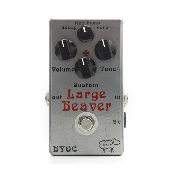
B.Y.O.C.
Large Beaver
build instructions.
page 2..............................................Parts Checklist
page 3 - 5.........................................Populating the Circuit Board
page 6 - 7.........................................Assembly
page 8..............................................Wiring
page 9 - 11.......................................Installing the LED
copyright 2006 b.y.o.c., LLC
Advertisement

Related Manuals for BYOC Large Beaver


Summary of Contents for BYOC Large Beaver
- Page 1 B.Y.O.C. Large Beaver build instructions. page 2..........Parts Checklist page 3 - 5.........Populating the Circuit Board page 6 - 7.........Assembly page 8..........Wiring page 9 - 11........Installing the LED copyright 2006 b.y.o.c., LLC...
-
Page 2: Parts Checklist
Parts Checklist Resistors: 1 150ohm (brown/green/brown/gold) 2 820ohm (gray/red/brown/gold) 1 1k (brown/black/red/gold) 1 2.7k (red/purple/red/gold) 1 3.3k (orange/orange/red/gold) 1 4.7k (yellow/purple/red/gold) 2 8.2k (gray/red/red/gold) 2 12k (brown/red/orange/gold) 2 22k (red/red/orange/gold) 2 39k (orange/white/orange/gold) 2 82k (gray/red/orange/gold) 1 100k (brown/black/yellow/gold) 4 390k (orange/white/yellow/gold) 1 1m (brown/black/green/gold) 2 100kA pot (volume and sustain) 1 100kB pot (tonel) -
Page 3: Populating The Circuit Board
Populating the Circuit Board Step1: Install the diodes. Make sure the side with the stripe (cathode) lines up with the strip on the layout. Step 2: Install the resistors. These are not polarized so they can go in the circuit board in either direction. - Page 4 Step3: Install the transistors. Make sure that they line up with the layout. Step 4: install the film caps. These are not polarized and can go in the board in either direction.
- Page 5 Step 5: Install the ceramic disc caps. These are not polarized and can go in the circuit board in either direction.
- Page 6 Assembly 1. Install the jacks first. If you are looking down inside the enclosure, the mono jack goes on the right side and the stereo jack goes on the left. Place the washer on the outside of the enclosure. Use a 1/2" wrench to tighten. 2.
- Page 7 This is a disconnect ac adaptor jack. That means that when you have a battery connected and you plug in the adaptor, it will disconnect the battery. That is why there are 2 positive terminals. They are both connected when there is no plug in the jack, but when the plug is inserted only one of the terminals (the uppermost terminal in the back view ) is connected to the sleeve of the adaptor.
- Page 8 copyright 2006 b.y.o.c., LLC...
- Page 9 Installing the LED (light emmiting diode) So many people make the mistake of inserting the LED in through the top of the bezel. You insert the LED in through thebottom (newer kits will not have a bezel).
- Page 10 You will install the LED at the same time you mount the circuit board. 1. Insert the LED into its slot on the underside or solder side of the circuit board,but DO NOT SOLDER it yet. Make sure the anode(the long leg) goes in the round solder pad and the cathode(the short leg)goes in the square solder pad.
- Page 11 If you have any problems or questions, visit www.buildyourownclone.com/board for tech support. copyright 2006 b.y.o.c., LLC...
Need help?
Do you have a question about the Large Beaver and is the answer not in the manual?
Questions and answers