Advertisement
Quick Links
Build Your Own Clone
Tremolo
Kit Instructions
Warranty:
BYOC, LLC guarantees that your kit will be complete and that all parts and components
will arrive as described, functioning and free of defect. Soldering, clipping, cutting,
stripping, or using any of the components in any way voids this guarantee. BYOC, LLC
guarantees that the instructions for your kit will be free of any majors errors that would
cause you to permanently damage any components in your kit, but does not guarantee
that the instructions will be free of typos or minor errors. BYOC, LLC does not
warranty the completed pedal as a whole functioning unit nor do we warranty any of the
individual parts once they have been used. If you have a component that is used, but
feel it was defective prior to you using it, we reserve the right to determine whether or
not the component was faulty upon arrival. Please direct all warranty issues to:
sales@buildyourownclone.com This would include any missing parts issues.
Return:
BYOC, LLC accepts returns and exchanges on all products for any reason, as long as
they are unused. We do not accept partial kit returns. Returns and exchanges are for the
full purchase price less the cost of shipping and/or any promotional pricing. Return
shipping is the customers responsiblity. This responsibility not only includes the cost of
shipping, but accountability of deliver as well. Please contact
sales@buildyourownclone.com to receieve a return authorization before mailing.
Tech Support:
BYOC, LLC makes no promises or guarantees that you will sucessfully complete your kit
in a satisfactory mannor. Nor does BYOC, LLC promise or guarantee that you will
Advertisement

Related Manuals for BYOC Tremolo


Summary of Contents for BYOC Tremolo
- Page 1 Kit Instructions Warranty: BYOC, LLC guarantees that your kit will be complete and that all parts and components will arrive as described, functioning and free of defect. Soldering, clipping, cutting, stripping, or using any of the components in any way voids this guarantee. BYOC, LLC...
- Page 2 That being said, we will do our best to help you as much as we can. Our philosophy at BYOC is that we will help you only as much as you are willing to help yourself. We have a wonderful and friendly DIY discussion forum with an entire section devoted to the technical support and modifications of BYOC kits.
-
Page 3: Table Of Contents
TREMOLO INSTRUCTION INDEX Parts Checklist ....page 4 - 5 Completed Example..........page 6 Populating the Circuit Board ....page 7 - 14 Main PCB Assembly .........page 15 - 17 Wiring the Jacks............page 18 - 19 Footswitch Assembly..........page 20 - 23 Operation Overview..........page 24... -
Page 4: Parts Checklist
Parts Checklist for BYOC Tremolo Resistors: 1 - 180 ohm (brown/gray/black/black/brown) 2 - 1k (brown/black/black/brown/brown) 1 - 4k7 (yellow/purple/black/brown/brown) 2 - 10k (brown/black/black/red/brown) 1 - 15k (brown/green/black/red/brown) 1 - 100k (brown/black/black/orange/brown) 1 - 150k (brown/green/black/orange/brown) 1 - 560k (green/blue/black/orange/brown) 3 - 1M (brown/black/black/yellow/brown) - Page 5 1 - A100k audio (Level knob) Hardware: 1 - drilled enclosure w/ 4 screws 1 - byoc tremoloPCB 1 - mono Footswitch PCB (not included in Rev 3.1 kits) 1 - 2 x 4 pin header (not included in Rev 3.1 kits) 1 - 2 x 4 pin header socket (not included in Rev 3.1 kits)
-
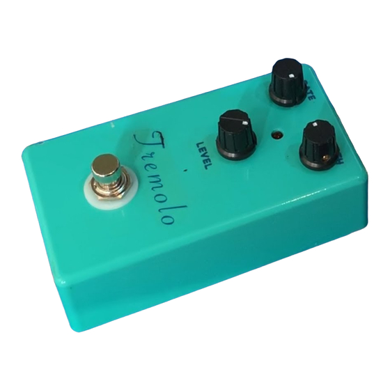
Page 6: Completed Example
Note: This is an example of the Rev3.1 PCB without footswitch PCB... -
Page 7: Populating The Circuit Board
Populating the Circuit Board STEP 1: Add the diode. Be sure to matched the end of the diode with the stripe to the layout on the PCB. The stripped end should go in the square solder pad. - Page 8 STEP 2: Add the resistors . Resistors are not polarized, so it does not matter which end goes in which solder pad.
- Page 9 Rev 3.1 kits will not include a header socket. Skip this step if your kit came with a Rev 3.1 PCB. Step 3: Add the 4 x 2 pin header socket. Make sure you are adding the female socket, not the male header.
- Page 10 STEP 4: Add the film capacitors. These are not polarized so they can be inserted into the PCB in either direction.
- Page 11 STEP 5: Add the transistors. Orient the transistors so that the flat side matches up with the flat side of the PCB layout. Be sure to put the 2N5088's in the spaces highlighted in yellow and the 2N5457's in the spaces highlighted in red.
- Page 12 STEP 6: Add the aluminum electrolytic capacitors. These are polarized. The positive end will have a longer lead and should go in the square solder pad. The negative end will have a shorter lead with a black strip running down the body of the capacitor.
- Page 13 Step 7: Add the battery snap. Thread the solder ends of the battery snap into the strain relief holes from the bottom solderside of the PCB and out through the top. Insert the solder ends of the battery snap wires into the topside of their respective solder pads. Solder on the bottom side of the PCB.
- Page 14 Step 8: Add wires to the IN, OUT, Ground, and RING eyelets. Start by cutting four 2.5 pieces of wire and one 1.5 piece of wire. Strip 1/4 off each end and tin the ends. Tinning means to apply some solder to the stripped ends of the wires. This keeps the strands from fraying and primes the wire for soldering.
-
Page 15: Main Pcb Assembly
Assembly Step 1: Mount the DC adaptor jack to the enclosure. Step 2: Connect the TIP (negative) terminal of the DC adaptor jack to the eyelet on the PCB with 2 inches of hook up wire. Connect the SLEEVE of the DC adaptor jack to the eyelet on the far right side of the PCB with 2 inches of hook up wire. - Page 16 Step 3: Flip the PCB over so that the bottom or solder side is up. Insert the B1M(depth), A100k(level), C100K(rate) potentiometers, and the LED into the bottom side of the PCB. DO NOT SOLDER YET!!! The LED will have one lead that is longer than the other. The longer lead goes in the hole with the square solder pad.
- Page 17 Step 4: Hold the PCB in one hand so that the component side of the PCB is in the palm of your hand and the bottom side with the pots, toggle switch and LED is facing up. Now use your other hand to guide the predrilled enclosure onto the PCB assembly so that the pots and LED all go into their respective holes.
-
Page 18: Wiring The Jacks
Wiring the jacks Step 1: Install the 1/4 jacks to the enclosure. Be sure to turn the OUT jack a 1/4 turn counter clockwise so that solder terminal for the tip does not short out against the enclosure. - Page 19 Step 2: Connect the pre stripped and tinned wires to the 1/4 jacks.
-
Page 20: Footswitch Assembly
Footswitch Wiring/Assembly Kits with Rev3.1 PCBs will have a wired footswitch. Kits with a Rev 3.0 PCB will have a PC mounted footswitch. If your kit came with a Rev 3.1 PCB, please continue with the instructions and skip pages 22 - 23. If your kit came with a Rev 3.0 PCB, please skip page 21. - Page 21 Wiring the Footswitch...
- Page 22 Installing the PC Mounted Footswitch Top Side of Footswitch PCB Make sure that the footswitch and 2 x 4 header go into the underside of the footswitch PCB. Not the topside. You will solder on the topside of the PCB. But do not solder anything yet.
- Page 23 Insert the header all the way into the header socket and mount the footswitch to the enclosure. Adjust the height of the inner footswitch nut so that the footswitch pcb lies flat on both the footswitch and header and is parallel to the main PCB, i.e., adjust the inner footswitch nut so that everything fits nice.
-
Page 24: Operation Overview
Operating Overview Pretty simple. Volume, Depth, Rate. Guitar plugs in on the left. Amp plugs in on the right. DC power supply - Use a 2.5mm negative tip 9VDC adaptor (this is your standard guitar fx style adaptor). If using battery power, only use a single 9V battery. Current Draw - 3.5mA Input Impedance - 1M ohms Output Impedance - 100k ohms... - Page 26 Please visit http://buildyourownclone.com/board for any technical support copyright 2009 B.Y.O.C., LLC...
Need help?
Do you have a question about the Tremolo and is the answer not in the manual?
Questions and answers