Advertisement
Advertisement

Related Manuals for DEVI DEVIreg 132


Summary of Contents for DEVI DEVIreg 132
- Page 1 Installation Guide DEVIreg™ 132 Electronic Thermostat www.DEVI.com...
-
Page 3: Table Of Contents
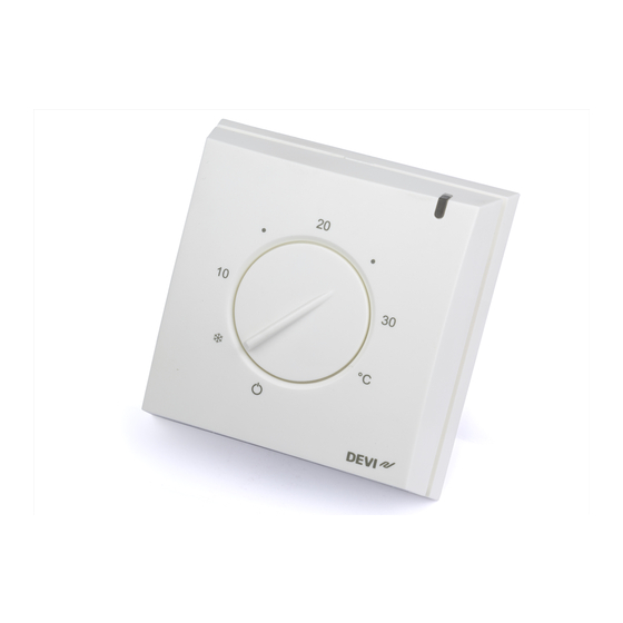
The thermostat has a button for adjusting the temperature, with a scale from ( ) 5-45°C, and an LED indicator showing standby (green light) and heating periods (red light). More information on this product can also be found at: devireg.devi.com Installation Guide... -
Page 4: Technical Specifications
DEVIreg™ 132 Technical Specifications Operation voltage 220-240V~, 50Hz Standby power consump- Max 5W tion Relay: Resistive load Max 16A / 3680W @ 230V Inductive load cos φ= 0.3 max 1A Sensing units NTC 15 kOhm at 25°C Sensing values: 0°C 42 kOhm 25°C 15 kOhm... -
Page 5: Safety Instructions
DEVIreg™ 132 Type Storage temperature -20 to +65°C IP class Protection class Class II - Dimensions 82 x 82 x 36mm Weight The product complies with the EN/IEC Standard "Automatic electrical controls for household and similar use": ▪ EN/IEC 60730-1 (general) ▪... -
Page 6: Mounting Instructions
DEVIreg™ 132 Please also note the following: ▪ The installation of the thermostat must be done by an authorized and qualified installer according to local regulations. ▪ The thermostat must be connected to a power supply via an all-pole disconnection switch. ▪... - Page 7 DEVIreg™ 132 Do not place the thermostat on the inner side of an exterior wall. Always install the thermostat at least 50 cm from windows and doors. Do not place the thermostat in a way that it will be exposed to direct sunlight. Note: A floor sensor enables a more accurate tem- perature control and is recommended in all floor heating applications and mandatory under wood-...
- Page 8 DEVIreg™ 132 ▪ The conduit should be flush with the floor surface - countersink the conduit if necessary. ▪ Route the conduit to the connection box. ▪ The bending radius of the conduit must be min 50mm. Follow the steps below to mount the thermostat: 1.
- Page 9 DEVIreg™ 132 2. Fasten the thermostat directly to the wall by driving the screws through the holes in each side of the ther- mostat. = Screw holes for fastening the thermostat. 3. Connect the thermostat according to the connection diagram. LOAD LOAD Max.Load...
-
Page 10: Settings
DEVIreg™ 132 4. Set the maximum floor temperature between 20˚ and 50˚C by using a thin screwdriver on the black elec- tronic component with temperature indications in the upper right corner. 5. Install the front cover and button in the reverse order of disassembly. - Page 11 DEVIreg™ 132 Please be aware of the following: ▪ The floor temperature is measured where the sensor is placed. ▪ The temperature of the bottom of a wooden floor can be up to 10 degrees higher than the top. ▪ Floor manufactures often specify the max tempera- ture on the top surface of the floor (usually 27-28˚C).
-
Page 12: Warranty
DEVIreg™ 132 Thermal Examples of floor- Details Approximate resist- setting for ance 25˚C floor [m2K/W] temperature 0.05 8 mm HDF based 28˚C > 800 kg/m laminate 0.10 14 mm beech par- 650 - 800 31˚C quet kg/m 0.13 22 mm solid oak 32˚C >... -
Page 13: Disposal Instruction
DEVIreg™ 132 Disposal Instruction Installation Guide... - Page 14 DEVIreg™ 132 Installation Guide...
- Page 15 This also applies to products already on order provided that such alterations can be made without subsequential changes being necessary in specifications already agreed. All trademarks in this material are property of the respective companies. DEVI and the DEVI logo- type are trademarks of Danfoss A/S.
Need help?
Do you have a question about the DEVIreg 132 and is the answer not in the manual?
Questions and answers