Advertisement
Advertisement

Subscribe to Our Youtube Channel
Related Manuals for DEVI DEVIreg 130


Summary of Contents for DEVI DEVIreg 130
- Page 1 Installation Guide DEVIreg™ 130 Electronic Thermostat www.DEVI.com...
-
Page 3: Table Of Contents
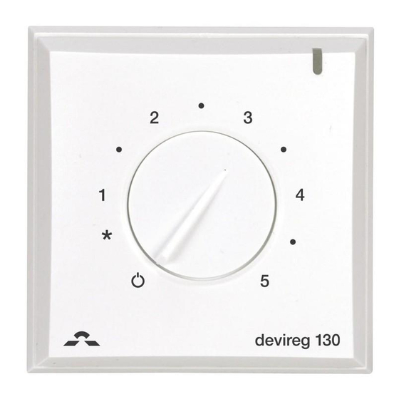
( ) 1 to 5 (each step corresponds to approximately 9°C). Furthermore, the thermostat has an LED indicator showing standby periods (green light) and heating periods (red light). More information on this product can also be found at: devireg.devi.com Installation Guide... -
Page 4: Technical Specifications
DEVIreg™ 130 Technical Specifications Operation voltage 220-240V~, 50Hz Power consumption Max 5W Relay: Resistive load Max 16A / 3680W @ 230V Inductive load cos φ= 0.3 max 1A Sensing units NTC 15 kOhm at 25°C Sensing values: 0°C 42 kOhm 25°C 15 kOhm 50°C... -
Page 5: Safety Instructions
DEVIreg™ 130 IP class Protection class Class II - Dimensions 82 x 82 x 36mm Weight The product complies with the EN/IEC Standard "Automatic electrical controls for household and similar use": ▪ EN/IEC 60730-1 (general) ▪ EN/IEC 60730-2-9 (thermostat) Safety Instructions Make sure the mains supply to the thermostat is turned off before installation. -
Page 6: Mounting Instructions
DEVIreg™ 130 ▪ The sensor is to be considered as live voltage. Have this in mind if the sensor must be extended. ▪ Always connect the thermostat to continuous power supply. ▪ Do not expose the thermostat to moisture, water, dust, and excessive heat. - Page 7 DEVIreg™ 130 ▪ Place the floor sensor in a conduit in an appropriate place where it is not exposed to sunlight or draft from door openings. ▪ Equally distant and >2cm from two heat- ing cables. ▪ The conduit should be flush with the floor surface - countersink the conduit if neces- sary.
- Page 8 DEVIreg™ 130 Follow the steps below to mount the thermostat: 1. Open the thermostat: ▪ Lift off the button using a small screwdriver. ▪ Loosen the screw which holds the front. ▪ Push down the release tab at the top of the thermo- stat using a flat object while slowly pulling off the front cover.
- Page 9 DEVIreg™ 130 2. Fasten the thermostat directly to the wall by driving the screws through the holes in each side of the ther- mostat. = Screw holes for fastening the thermostat. 3. Connect the thermostat according to the connection diagram. LOAD LOAD Max.Load...
-
Page 10: Settings
DEVIreg™ 130 4. Install the front cover and button in the reverse order of disassembly. 5. Turn on the power supply. Settings Temperature Settings How to change the minimum and maximum floor tem- peratures 1. Lift off the adjustment button using a thin screwdriver. - Page 11 DEVIreg™ 130 ▪ Floor manufactures often specify the max temperature on the top surface of the floor (usually 27-28˚C). ▪ By default, the maximum floor temperature is set to 35°C. ▪ Always use a floor sensor or a room + floor sensor combination to control floor heating.
-
Page 12: Warranty
DEVIreg™ 130 Warranty Y E A R Disposal Instruction Installation Guide... - Page 13 DEVIreg™ 130 Installation Guide...
- Page 14 DEVIreg™ 130 Installation Guide...
- Page 15 This also applies to products already on order provided that such alterations can be made without subsequential changes being necessary in specifications already agreed. All trademarks in this material are property of the respective companies. DEVI and the DEVI logo- type are trademarks of Danfoss A/S.
Need help?
Do you have a question about the DEVIreg 130 and is the answer not in the manual?
Questions and answers