Table of Contents
Advertisement
Quick Links
Instructions and Parts List
3M-Matic
800rf
Type 40800
Random
Case Sealer
with
AccuGlide 3
Taping Heads
Serial No.
For reference, record machine serial number here.
3M Industrial Adhesives and Tapes
3M Center, Building 220-5E-06
St. Paul, MN 55144-1000
™
™
Important Safety
Information
BEFORE INSTALLING
OR OPERATING THIS
EQUIPMENT
Read, understand, and
follow all safety and
operating instructions.
Spare Parts
It is recommended you
immediately order the
spare parts listed in the
"Spare Parts/Service
Information" section.
These parts are expected
to wear through normal
use, and should be kept
on hand to minimize
production delays.
"3M-Matic"and "AccuGlide" are Trademarks of,
3M St. Paul, MN 55144-1000
Printed in U.S.A.
© 3M 2012 44-0009-2085-8 (B030912-NA)
Advertisement
Table of Contents

Related Manuals for 3M 3M-Matic 800rf


Summary of Contents for 3M 3M-Matic 800rf
- Page 1 Serial No. production delays. For reference, record machine serial number here. "3M-Matic"and "AccuGlide" are Trademarks of, 3M Industrial Adhesives and Tapes 3M St. Paul, MN 55144-1000 3M Center, Building 220-5E-06 Printed in U.S.A.
- Page 2 3M-Matic 800rf Random case sealer. 3M Industrial Adhesives and Tapes 3M Center, Building 220-5E-06 St. Paul, MN 55144-1000 Edition March 2012...
-
Page 3: Replacement Parts And Service Information
(For example: Model 800rf - Type 40800 - Serial Number 13282). Identifi cation Plate For Commercial Use Only 3M-Matic , AccuGlide and Scotch ™ ™ ™ 3M Industrial Adhesives and Tapes are Trademarks of 3M Center, Building 220-5E-06 3M St. Paul, MN 55144-1000 St. Paul, MN 55144-1000 Printed in U.S.A. - Page 4 THIS PAGE IS BLANK...
- Page 5 3M-Matic , AccuGlide and Scotch ™ ™ ™ 3M Industrial Adhesives and Tapes are Trademarks of 3M Center, Building 220-5E-06 3M, St. Paul, MN 55144-1000 St. Paul, MN 55144-1000 Printed in U.S.A.
- Page 6 THIS PAGE IS BLANK...
-
Page 7: Table Of Contents
TABLE OF CONTENTS - MANUAL 1: 800rf Random Case Sealer (For Taping Head Information - See MANUAL 2: AccuGlide 3 Taping Heads - 2 Inch) 800rf Random Case Sealer Page Cover Page Replacement Parts and Service Information ................ i - ii Table of Contents ......................... - Page 8 THIS PAGE IS BLANK...
- Page 9 TABLE OF CONTENTS (continued) 5. Shipment, Handling, and Storage 5.1 Packed Machine Shipment and Handling ................15 5.2 Overseas Shipment Packaging (Optional) ................. 15 5.3 Handling and Transportation of Uncrated Machine ............15 5.4 Machine Storage ........................ 15 6. Unpacking 6.1 Uncrating ..........................
- Page 10 THIS PAGE IS BLANK...
- Page 11 TABLE OF CONTENTS (continued) 12. Troubleshooting 12.1 Troubleshooting ......................39 - 40 13. Maintenance 13.1 Safety Measures (see section 3) ..................41 13.2 Tools and Spare Parts Supplied with Machine ..............41 13.3 Maintenance Operations - Recommended Inspections and Frequency ......41 13.4 Inspections to be Performed Before and After Every Maintenance Operation ....
- Page 12 ABBREVIATIONS AND ACRONYMS LIST OF ABBREVIATIONS, ACRONYMS 3M-Matic - Trademark of 3M St. Paul, MN 55144- 1000 AccuGlide - Trademark of 3M St. Paul, MN 55144-1000 Scotch - Trademark of 3M St. Paul, MN 55144-1000 Drw. - drawing - for example Fig.
-
Page 13: Introduction
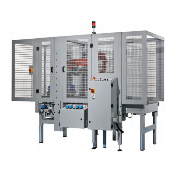
1.1 Manufacturing Specifi cations / Description / Intended Use The 3M-Matic™ Model 800rf Type 40800 Automatic Random Case Sealer with AccuGlide™ 3 Taping Heads is designed to accept fi lled, regular slotted containers from an existing conveyor, fold the top fl aps, and apply a “C”... -
Page 14: How To Read And Use The Manual
(ELV), a Modifi cations to the machine are subject to manu- defi nition of symbols, plus a parts list of the 3M-Matic facturer’s internal procedures. The user receives a 800rf Random case sealer 3M Industrial Adhesives complete and up-to-date copy of the manual to- and Tapes Division 3M Center, Bldg. -
Page 15: General Information
2-GENERAL INFORMATION 2.1 Data Identifying Manufacturer and Machine For Commercial Use Only 2.2 Data for Technical Assistance and Service 2012 March 800rf-NA... -
Page 16: Warranty / Contents
3M’s factory or an authorized service station designated by 3M. A part will be presumed to have become defective after its warranty period unless the part is received or 3M is notifi ed of the problem no later than fi... -
Page 17: Safety
3-SAFETY 3.1 General Safety Information 3.2 Explanation of Signal Word and Possible Consequences Read all the instructions carefully before starting work with the machine; please pay particular atten- tion to sections marked by the symbol: This safety alert symbol identifi es important messages in this manual. -
Page 18: Table Of Warnings
3-SAFETY (continued) 3.3 Table of Warnings WARNING • To reduce the risk associated with mechanical and electrical hazards: − Read, understand, and follow all safety and operating instructions before operating or servicing the case sealer. Figure 3-2 − Allow only properly trained and qualifi... - Page 19 3-SAFETY (continued) WARNING • To reduce the risk associated with sharp blade hazards: − Keep hands and fi ngers away from WARNING tape cutoff blades under orange blade Sharp Blade guards. The blades are extremely sharp. Important! Tape cutting blade. Never remove the safety device which covers the blade on the top and bottom taping units.
-
Page 20: Operator's Qualifi Cations Defi Nition
3-SAFETY (continued) 3.4 Operator's Qualifi cations WARNING - Machine Operator - Mechanical Maintenance Technician • To reduce the risk associated with - Electrical Maintenance Technician mechanical and electrical hazards: - Manufacturer’s Technician/Specialist − Read, understand, and follow all safety (See Section 3.11) and operating instructions before operating or servicing the case sealer. -
Page 21: Operator's Required Skill Levels
3-SAFETY (continued) Skill 2a: Electrical Maintenance Technician 3.11 Operator's Skill Levels Required to Perform This operator is trained to use the machine as the the Main Operations on the Machine MACHINE OPERATOR and in addition is able to: • Work with the safety protection disconnected The Table shows the minimum operator's skill for •... -
Page 22: Component Locations
3-SAFETY (continued) 3.12 Component Locations Refer to Figure 3-9 below to acquaint yourself with the various components and controls of the case sealer. Also refer to Manual 2 for taping head components. Top Taping Side Flap E-Stop Upper Head Head Folding Arm Switch Assembly... -
Page 23: Table Of Warnings And Replacement Labels
78-8070-1333-5 78-8113-6882-4 78-8070-1336-8 on Tape Head 78-8113-8912-9 78-8113-6883-2 78-8070-1366-5 78-8070-1317-8 78-8070-1331-9 78-8137-0886-0 78-8137-0221-0 78-8113-6750-3 78-8062-4266-1 78-8137-1331-6 78-8095-1141-9 78-8060-8481-6 78-8070-1339-2 78-8070-1329-3 3M Logo Leg Height Adjustment Label (not shown) (not shown) Figure 1-1 – Replacement Labels/3M Part Numbers 2012 March 800rf-NA... -
Page 24: Power Requirements
The machine is equipped with a 2.4m [8 foot] standard neoprene covered power cord and a grounded plug. Contact your 3M Representative for power requirements not listed above. Pneumatic – 6 bar gauge pressure [87 PSIG] @ 21 C, 1.01 bar [3.75 SCFM] at 15 boxes per minute A pressure regulator is included Machine requires 75 –... -
Page 25: Tape Roll Diameter
4-SPECIFICATIONS (continued) 4.6 Tape Roll Diameter Up to 410mm [16 inch] maximum on a 76.2mm [3 inch] diameter core. (Accommodates all system roll lengths of Scotch fi lm tapes.) ® 4.7 Tape Application Leg Length – Standard 70mm ± 6mm [2 3/4 inch ±1/4 inch] Tape Application Leg Length –... -
Page 26: Machine Noise Levels
4-SPECIFICATIONS (continued) 4.10 Machine Dimensions 3308mm 694mm 1520mm 1094mm 4.11 Machine Noise Level: Acoustic pressure measured at a distance of 1m. from machine with Scotch PVC adhesive tape in operation; 78dB Acoustic radiation pressure at 1.6m. height with Scotch PVC adhesive tape in operation; 73dB Measurement taken with appropriate instrument: (Type SPYRI-MICROPHON 11). -
Page 27: Shipment, Handling, And Storage 5.1 Packed Machine Shipment And Handling
5-SHIPMENT-HANDLING-STORAGE, TRANSPORT 5.1 Shipment and Handling of Packed Machine The machine and the infeed conveyor are shipped in 2 separate packings, fi xed on a wooden pallet. They can be uplift with a normal forklift. The standard pack- ing is suitable for surface and air transportation. Over- sea packing on request. -
Page 28: Unpacking
6-UNPACKING 6.1 Uncrating Removal of Pallet The envelope attached to the shipping box contains Loosen and remove nuts and brackets using the the uncrating instructions of the machine (Figure 6-1). open end spanner supplied in the tool box (Figure 6-4). Figure 6-1 Figure 6-4 A cardboard box is located under the machine body. -
Page 29: Installation
7-INSTALLATION 7.1 Operating Conditions The machine should operate in a dry and relatively WARNING clean environment (See Specifi cations). • To reduce the risk associated with 7.2 Space Requirements for Machine Operation muscle strain: and Maintenance Work − Use the appropriate rigging and Minimum distance from wall (Figure 7-1): material handling equipment when lifting or repositioning this equipment. -
Page 30: Plastic Ties Removal
7-INSTALLATION (continued) 7.5 Safety Guards: Inside and Outside Machine Emergency Stop Push-Button Position and assemble the inside (A) and outside (B) guard panels with the upper and bottom brackets and stiffening profi le plates as shown in the pictures Figure 7-4 (Figure 7-4). - Page 31 7-INSTALLATION (continued) (infeed conveyor attachment continued) Approach the infeed conveyor to the machine and fi x it using the screws previously removed (Figure 7-11). Figure 7-11 B10, B1, B2 infeed conveyor photocells connections (Figure 7-12). WARNING • To reduce the risk associated with mechanical and electrical hazards: Figure 7-12 −...
- Page 32 7-INSTALLATION AND SET-UP (continued) 7.6 Pneumatic & Control Board Connections (continued) - Connect an air tube to the ON/OFF valve and attach it with a strap. Minimum inside diameter of the tube 10mm; air pressure 6 BAR. Give air to the machine with the ON/OFF valve (Figure 7-15).
- Page 33 7-INSTALLATION AND SET-UP (continued) (Pneumatic & Control Board Connections - continued) Figure 7-19 Front junction box connector (Figure 7-20). Figure 7-20 Rear junction box connector. (Figure 7-21). Figure 7-21 2012 March 800rf-NA...
-
Page 34: Preliminary Electric Inspection
7-INSTALLATION AND SET-UP (continued) Preliminary Electric Check-Out Before connecting the machine to the mains please carry out the following operations: - Make sure that the socket is provided with a ground protection circuit and that both the mains voltage and frequency meet the indications on the name plate of the machine. -
Page 35: Completion Of Taping Head
7-INSTALLATION AND SET-UP (continued) 7.9 Completion of Taping Heads One Way See Manual 2 for Complete Instructions: Tension Roller 1. Place the Upper Taping Head in a convenient working position Tension .2. Use Figure 7-22 and tape threading label. Wrap Roller Position the tape supply roll so the adhesive side of tape is facing the front of the taping head... -
Page 36: Controls 8.1 Control Board
8-CONTROLS 8.1 Controls Board Main switch (Figure 8-1). Emergency stop push button (lockable) Auxiliaries push button (control board electrical components habilitation) Reset push button (new work cycle predisposition ) Start push button Stop push button Voltage warning light Thermal switch warning light Warning (fl... -
Page 37: Operation
9-OPERATION 9.1 Operation - Give air to the machine by the ON/OFF valve, set the main switch to ON (I) position; - Close the safety guards; release the E-stops; - Press AUXILIARIES button, - Press RESET button; press START button. The box, after passed the infeed conveyor belt, obscures the fi... - Page 38 9-OPERATION (continued) Simultaneously the rear fl ap is folded the fork goes down and the side belts restart to run (Figure 9-6). Figure 9-6 The side fl aps are folded (Figure 9-7). Figure 9-7 The two taping heads seal the box with adhesive tape (Figure 9-8).
-
Page 39: Operation Methods
9-OPERATION (continued) Important! If, for any reason, the box should stop inside the machine, the machine will stop operating after 10 seconds. To remove the box and restart, operate as follows: - press the E-stop, - open the safety guard, - remove the box, - close the safety guard an release the E-stops, - press the AUXILIARIES push-button;... -
Page 40: Alarms
9-OPERATION (continued) 9.4 Alarms Warning light a: Thermal switch activation (motor overload) The machine cannot be started; machine stops if it is running To restart press 3, after 4, then 5 push-buttons. Warning light b: Time out cycle (the machine will stop when the cycle taping boxes is not done just in time as preselected;... -
Page 41: Safety Devices 10.1 Blade Guards
10-SAFETY DEVICES OF THE MACHINE 10.1 Blade and Safety Guards 3308mm Both the top and bottom taping units have a blade guard (See Manual 2: AccuGlide™ 3 Taping Heads - 2 Inch). E-Stop WARNING Power • To reduce the risk associated with Start Rear E-Stop Stop... -
Page 42: Set-Up And Adjustments
11 - SET UP AND ADJUSTMENTS 11.1 Tape Loading on the Top Unit Figure 11-1 Insert a tape roll on the drum and push it fully forward. Attach the tape leg to the threading tool (supplied with the tools kit) Figure 11-1. Figure 11-2 Insert the plastic threading leader through the taping unit. -
Page 43: Tape Loading On The Bottom Unit
11 - SET UP AND ADJUSTMENTS (continued) 11.2 Tape Loading on the Bottom Unit Remove the bottom taping unit from its housing and put it on a working bench (Figure 11-7). Put a tape roll on the drum and thread the tape through the unit as shown on the label in the same manner as for the top unit (Figure 11-8). -
Page 44: Main Pressure Regulator
11 - SET UP AND ADJUSTMENTS (continued) Figure 11-11 11.6 Main Pressure Regulator A) it adjusts the entry working pressure B) gauge to read the entry air pressure Optimal working pressure: 6 BAR Feeding tube diameter: 10mm Note: in case the working pressure is below 6 BAR or the feeding tube has a small diameter, some malfunctions can happen! (ex: the upper group comes down, the rear fl... -
Page 45: Box Height Pick-Up
11 - SET UP AND ADJUSTMENTS (continued) 11.9 Box Height Pick-up 3) Pressure regulator with built-in pressure gauge. The pressure regulator 3 adjusts the pressure according to the board strength. Decrease in case of light boxes. Increase in case of strong boxes. Minimum pressure must be adjusted so that the paddle returns automatically in Figure 11-16... -
Page 46: Pneumatic Speed Regulators
11 - SET UP AND ADJUSTMENTS (continued) 11.11 Pneumatic Speed Regulators A) Upper unit ascent-descent speed regulators B) Centering guides (infeed conveyor) speed regulators C) Side belts opening-closing speed regulators Side belts opening-closing speed regulators. These are not common operations. They have to be made only when it has been necessary to work on the pneumatic cylinder. -
Page 47: Speed Regulators Of The Rear Flap Folder
11 - SET UP AND ADJUSTMENTS (continued) 11.12 Speed Regulators of the Rear Flap Folder These are not common operations. They have to be made only when it has been necessary to work on the pneumatic cylinder. To change the speed, do as follows: The speed of the rear fl... -
Page 48: Adjustment Of The Sensor That Stops The Descent Of The Upper Unit
11 - SET UP AND ADJUSTMENTS (continued) 11.14 Adjustment of the Sensor that Stops the Descent of the Upper Unit The descent of the upper group is stopped when the sensor 1 is activated (yellow led up). The sensor is mounted on the cylinder 2 by the support 3. -
Page 49: Adjustments Of The Side Compression Rollers
11 - SET UP AND ADJUSTMENTS (continued) 11.15 Adjustments of the Side Compression Rollers To increase or decrease the pressure of the side rollers on the box, do as follows: loosen the nuts; change the position of the rollers; lock the nuts. Figure 11-32 increase the pressure when the upper fl... -
Page 50: Use And Adjustments Of The Photocells
11 - SET UP AND ADJUSTMENTS (continued) Figure 11-36 11.17 Use and Adjustments of the Photocells Photocell 1 The photocell does not operate at the fi rst machine starting ; when it is obscured by the next box the motorized plane of the infeed conveyor stops. -
Page 51: Troubleshooting
12-TROUBLE-SHOOTING The Troubleshooting Guide lists some possible machine problems, causes and corrections. Also see Manual 2 "Troubleshooting" for taping head problems. 12.1 Troubleshooting Guide Correction Problem Cause Tape is not centered on the box. Check the position. The side belts are not correctly positioned. - Page 52 12-TROUBLE-SHOOTING (continued) Troubleshooting Guide Problem Cause Correction The box is not dragged under the The box is too full load; box side Check. head. fl aps are opened. Replace as necessary. Driving pulley rings on motorizing Replace valve side units are worn out. Check pressure value (working Motorizing side units low pressure)
-
Page 53: Safety Measures (See Section 3)
13-MAINTENANCE AND REPAIRS 13.1 Safety Measures (see section 3) 13.2 Tools and Spare Parts Supplied with the Machine Carrying out maintenance and repairs may imply the necessity to work in dangerous situations. See Spare Parts Order Section. 13.3 Recommended Frequency of Inspection and Maintenance Operations Operation Frequency Qualifi... -
Page 54: Securities Check-Up
13-MAINTENANCE AND REPAIRS (continued) 13.8 Securities Check-up 1) Tape units blade guards; 2) Lockable emergency stop push-buttons; 3) Rigid protection plate mounted on the side drives; 4) Safety guards; 13.9 Machine Lubrication Lubricate quarterly with grease/Metal/metal Figure 13-1 1) Slide cross bar ball guides for side drives (grease nipples on the blocks) ;... -
Page 55: Drive Belt Replacement
Maintenance (continued) WARNING • To reduce the risk associated with mechanical and electrical hazards: − Turn electrical and air supply off and disconnect before performing any adjustments, maintenance or servicing the machine or taping heads • To reduce the risk associated with Figure 13-4 impact hazards: −... - Page 56 13-MAINTENANCE AND REPAIRS (continued) Remove the locking screws and the protection covers. Figure 13-9 Loosen the tensioning screws. Figure 13-10 Release the nut of the tensioning plate. Figure 13-11 Remove and replace the drive belt. Important Before setting the new belt, check the wear of the orange plastic rings on the drive Figure 13-12 pulleys: replace them if they are worn out.
-
Page 57: Box Drive Belt Tension
Adjustments (continued) 13.12 Box Drive Belt Tension The two (2) continuously moving drive belts convey boxes through the tape applying mechanism. The box drive belts are powered by an electric gear motor. Tension adjustment of these belts may be required during normal operation. Belt tension must be adequate to positively move the box through the machine and the belts should run fully on the surface of the pulleys at each end of the frame. - Page 58 THIS PAGE IS BLANK...
-
Page 59: Maintenance Work Log
13-MAINTENANCE AND REPAIRS (continued) 13.14 List of the Maintenance Operations Date: Description of Operation ________ ________________________________________________________________ ________ ________________________________________________________________ ________ ________________________________________________________________ ________ ________________________________________________________________ ________ ________________________________________________________________ ________ ________________________________________________________________ ________ ________________________________________________________________ ________ ________________________________________________________________ ________ ________________________________________________________________ ________ ________________________________________________________________ ________ ________________________________________________________________ ________ ________________________________________________________________ ________ ________________________________________________________________ ________ ________________________________________________________________ ________... - Page 60 THIS PAGE IS BLANK...
-
Page 61: Additional Instructions
14-ADDITIONAL INSTRUCTIONS 15-ENCLOSURES / SPECIAL INFO. 14.1 Information for Disposal of Machine 15.1 Statement of Conformity The machine is composed of the following materials: See Section 1. - Steel structure - Nylon rollers 15.2 Emission of Hazardous Substances - Drive belts in PVC Nothing to report - Nylon pulleys For machine disposal, follow the regulations... - Page 62 THIS PAGE IS BLANK...
-
Page 63: Technical Documentation And Information 16.1 Electric Diagrams
16-Electrical Technical Diagram WARNING • To reduce the risk associated with mechanical and electrical hazards: − Turn electrical and air supply off and disconnect before performing any adjustments, maintenance or servicing the machine or taping heads 2012 March 800rf-NA... - Page 64 16-TECHNICAL DIAGRAMS 16.1 Electric Diagram - Page 2A (see next Page 2B) 2012 March 800rf-NA...
- Page 65 16-TECHNICAL DIAGRAMS (continued) 16.1 Electric Diagram - Page 2B (see previous Page 2A) 2012 March 800rf-NA...
-
Page 66: Pneumatic Diagrams
16-Pneumatic Technical Diagram 2012 March 800rf-NA... -
Page 67: Spare Parts / Ordering
16-TECHNICAL DOCUMENTATION AND INFORMATION (continued) 16.3 Spare Parts Order The following parts are normal wear items and should be ordered and kept on hand as used. Qty. Part Number Description 78-8054-8841-4 Belt – Drive W/Pin Also see Manual 2 for recommended taping head spare parts. Label Kit In the event that any labels are damaged or destroyed, they must be replaced to ensure operator safety. - Page 68 THIS PAGE IS BLANK...
- Page 69 Important – Not all the parts listed are normally stocked items. Some parts or assemblies shown are available only on special order. Contact 3M/Tape Dispenser Parts to confi rm item availability. Options and Accessories For additional information on the options and accessories listed below, contact your 3M Representative.
- Page 70 THIS PAGE IS BLANK...
- Page 71 800rf Random Case Sealer Figure 15077 Figure 15076 Figure 10440 Figure 15071 Figure 15072 Figure 15294 15082 All Pneumatic Components and Plumbing Figure 15075 Figure 15295 Figure 15079 Figure 15078 Figure 15096 Figure 15073 See End of Manual for Infeed Conveyor Illustrations and Parts Lists.
- Page 72 800rf 800rf Figure 15071 2012 800rf-NA...
- Page 73 800rf Figure 15071 Ref. No. 3M Part No. Description 15071-1 78-8119-8507-2 Support Assy - Guide, R/H 15071-2 78-8119-8508-0 Support - Guide, L/H 15071-3 78-8137-3606-9 Height Positioner 15071-4 78-8060-7568-1 Bearing 618/9 / 9 -17-4 15071-5 78-8076-5081-3 Fork - Cylinder 15071-6 78-8060-7566-5...
- Page 74 800rf Figure 10440 2012 800rf-NA...
- Page 75 800rf Figure 10440 Figure 10440 Ref. No. 3M Part No. Description 10440-1 78-8070-1564-5 Tape Roll Bracket Assembly 10440-2 78-8070-1565-2 Tape Drum Bracket Assembly 10440-3 78-8070-1566-0 Bracket – Tape Drum 10440-4 78-8070-1395-4 Bracket – Bushing Assembly 10440-5 78-8070-1568-6 Cap – Bracket...
- Page 76 800rf Figure 15072 2012 800rf-NA...
- Page 77 800rf Figure 15072 Ref. No. 3M Part No. Description 15072-1 78-8137-3607-7 Frame - Upper Head- R/H 15072-2 78-8137-3608-5 Frame - Upper Head- L/H 15072-3 78-8137-3609-3 Screw - M8 X 20 15072-4 78-8017-9318-9 Washer-Plain-Metric M8 15072-5 78-8017-9313-0 Nut Self Locking M8 Nick. Pl.
- Page 78 800rf Figure 15073 2012 800rf-NA...
- Page 79 800rf Figure 15073 Ref. No. 3M Part No. Description 15073-1 78-8137-3613-5 Frame - Bottom Head- R/H 15073-2 78-8137-3614-3 Frame - Bottom Head- L/H 15073-3 78-8054-8862-0 Spacer - 12 X 12 X 1 - M40 Washer - Flat M6 15073-4 78-8010-7169-3 Screw - Metric, M6 X 12, Hex Hd..
- Page 80 800rf Figure 15074 2012 800rf-NA...
- Page 81 800rf Figure 15074 Ref. No. 3M Part No. Description 15074-1 78-8137-3618-4 Crossbar- Drive Assy Guides 15074-2 78-8137-3619-2 Sprocket - 3/8" Assy 15074-3 78-8137-3620-0 Sprocket - 3/8" - 35 Teeth 15074-4 78-8023-2551-0 Bearing - 6005-2RS 15074-5 78-8137-3621-8 Stop Ring 15074-6 78-8052-6709-9...
- Page 82 800rf Figure 15075 2012 800rf-NA...
- Page 83 800rf Figure 15075 Ref. No. 3M Part No. Description 15075-1 78-8137-3634-1 Bottom Plate For Side Roller R/H 78-8137-3635-8 Bottom Plate For Side Roller L/H 15075-2 78-8137-3636-6 Top Plate For Side Roller 15075-3 78-8137-3637-4 Block For Union Plates 15075-4 26-1001-9843-6 Screw Flat Soc. Hd.M6 X 16...
- Page 84 800rf Figure 15076 2012 800rf-NA...
- Page 85 800rf Figure 15076 Ref. No. 3M Part No. Description 15076-1 78-8137-3647-3 Outer Column Assy - R/H 78-8137-3648-1 Outer Column Assy - L/H 15076-2 26-1003-7964-8 Screw Soc. Hd. Hex Soc. Dr., M8 X 20 15076-3 78-8137-3649-9 Rail - Linear Guide 15076-4 78-8076-5477-3 Washer - Special / 6.5 X 20 X 4...
- Page 86 800rf 18 19 19 18 37 33 46 47 48 50 49 48 50 49 48 23 43 Figure 15077 2012 800rf-NA...
- Page 87 Figure 15077 Ref. No. 3M Part No. Description 15077-1 78-8137-3661-4 Support - Side Flap Folder 15077-2 78-8137-3662-2 Arm - Rear Flap Folder 15077-3 78-8137-3663-0 Support NSK 15077-4 78-8137-3664-8 Spacer - Flap Folder 15077-5 78-8119-8809-2 Rear Flap Folder Assy 15077-6 78-8119-8811-8...
- Page 88 800rf Figure 15078 2012 800rf-NA...
- Page 89 800rf Figure 15078 Ref. No. 3M Part No. Description 15078-1 78-8137-3672-1 Fixing Bracket, Box 15078-2 26-1004-5507-5 Washer M8 15078-3 26-1003-5842-8 Screw Hex Hd.. M8 X 20 15078-4 78-8137-3673-9 Fixing Spacer, Box 15078-5 78-8091-0656-6 Screw - Hex. Soc. Hd. M8 X 12...
- Page 90 800rf 800rf Random Case Sealer 36 37 34 17 Optional OPTIONAL Figure 15079 / 1 2012 800rf-NA...
- Page 91 800rf Figure 15079 / 1 Ref. No. 3M Part No. Description 15079-1 78-8137-3681-2 Frame - Conveyor 15079-2 78-8129-6370-6 Leg Assy 15079-3 78-8137-3682-0 Leg Assy L=600 15079-4 78-8129-6096-7 15079-5 78-8129-6371-4 Label - Leg 15079-6 78-8137-0641-9 Pad - Foot 15079-7 78-8137-3683-8 Leg - Inner...
- Page 92 800rf Random Case Sealer 800rf Figure 15079 / 2 2012 800rf-NA...
- Page 93 800rf Figure 15079 / 2 Ref. No. 3M Part No. Description 15079-1 78-8137-3703-4 Support - Plate Connectors 15079-2 26-1003-7957-2 Screw Soc. Hd. Hex Hd.. M6 X 16 15079-3 26-1000-0010-3 Washer - Flat M6 15079-4 78-8137-3704-2 Carter Protection Connectors 15079-5 26-1003-5820-4 Screw - Hex Hd..M-5 X 12...
- Page 94 800rf Random Case Sealer 800rf Figure 15082 / 1 2012 800rf-NA...
- Page 95 800rf Figure 15082 / 1 Ref. No. 3M Part No. Description 15082-1 78-8137-3745-5 Pneumatic Unit 15082-2 78-8137-3746-3 Regulator - Air Pressure 0-6 ATM 15082-3 78-8137-3747-1 Regulator - Air Pressure 0-10 ATM 15082-4 78-8119-8618-7 Union - Multiple, 33041008 15082-5 78-8076-4664-7 Union - Female...
- Page 96 800rf 800rf Random Case Sealer Figure 15082 / 2 2012 800rf-NA...
- Page 97 800rf Figure 15082 / 2 Ref. No. 3M Part No. Description 15082-31 78-8119-8640-1 Union - Elbow, 31820600 15082-32 78-8057-5735-4 Fitting - Reducer 15082-33 78-8091-0350-6 Union - Special 15082-34 78-8076-4666-2 Elbow - Bulkhead 15082-35 78-8013-9935-9 Valve - Quick Exhaust 15082-36 26-1005-6909-9...
- Page 98 800rf Figure 15082 / 3 2012 800rf-NA...
- Page 99 800rf Figure 15082 / 3 Ref. No. 3M Part No. Description 15082-46 78-8137-3765-3 Linear Unit DFM-40-B-P-A-KF 15082-47 78-8137-3766-1 Flow Regulator 15082-48 26-1017-3315-7 Swinging Flange 15082-49 78-8076-5170-4 Cylinder DNU-40-100-PPV-A-SN 15082-50 78-8091-0315-9 Elbow - 3199.08.13 15082-51 78-8137-3767-9 Cylinder DNC-40-170-PPV-A 15082-52 26-1017-3315-7 Swinging Flange...
- Page 100 800rf 58 71 58-71 3-70 2-69 76 91 76-91 Figure 15294 / 1 2012 800rf-NA...
- Page 101 800rf Figure 15294 / 1 Ref. No. 3M Part No. Description 15294-1 78-8137-3773-7 Drive Assy - R/H 15294-2 78-8137-3774-5 Guide - Lower, R/H 15294-3 78-8137-3775-2 Guide - Upper, R/H 15294-4 78-8054-8910-7 Spacer - Hexagonal 15294-5 78-8010-7169-3 Screw-Metric, M6 X 12, Hex Hd..
- Page 102 800rf 800rf Random Case Sealer Figure 15294 / 2 2012 800rf-NA...
- Page 103 800rf Figure 15294 / 2 Ref. No. 3M Part No. Description 15294-57 78-8060-8140-8 Belt-Timing 160 X L050 15294-58 78-8137-3785-1 Cover - Drive, Right 15294-59 78-8137-3786-9 Cover - Drive, Rear 15294-60 78-8129-6100-7 Bracket 15294-61 26-1002-4955-1 Screw - Self Tapping 8P X 13...
- Page 104 800rf Random Case Sealer 800rf Figure 15295 2012 800rf-NA...
- Page 105 800rf Figure 15295 Ref. No. 3M Part No. Description 15295-1 78-8137-3717-4 Jamb Assy 15295-2 78-8137-3718-2 Bracket - Guard 15295-3 78-8137-3719-0 Crossbar- Guard 15295-4 78-8137-3720-8 Support - Guard 15295-5 78-8137-3721-6 Closure Plate 15295-6 78-8017-9066-4 Screw - Metric, M5 X 12 15295-7 78-8010-7417-6 Nut - Metric, Hex Stl.
- Page 106 800rf Random Case Sealer 800rf Figure 15096 / 1 Figure 15296 / 1 2012 800rf-NA...
- Page 107 800rf Figure 15296 / 1 Ref No 3M Part Number Description 15296-1 78-8137-3737-2 Box - Electric 15296-2 78-8137-3738-0 Panel - Electric Box 15296-3 78-8060-7814-9 Spacer, Electric Box 15296-4 78-8010-7418-4 Nut - Metric, Hex, Stl., M6 15296-5 26-1000-0010-3 Washer - Flat M6...
- Page 108 800rf 70-72 39-40 25-26-27 28-29 30-31-73 35-36 33-34 37-38 32 78-8119-8945-4 41-42 45-46 41-42 47-48 47-48 47-48 47-48 52-53-54-55 56-53-54-55 49-50-51 HL15 HL14 HL12 HL11 HL10 HL13 Line Break / End Emergency Cycle Voltage Red Indicator Full tape Pressure Closing Time to Indicator Light Thermal...
- Page 109 800rf Figure 15296 / 2 Ref No 3M Part Number Description 15296-41 78-8137-6015-0 Relays G2R-2 24VDC 15296-42 78-8137-4085-5 Socket 15296-43 78-8137-6015-0 Relays G2R-2 24VDC 15296-44 78-8137-4085-5 Socket 15296-45 78-8137-6015-0 Relays G2R-2 24VDC 15296-46 78-8137-4085-5 Socket 15296-47 78-8137-6017-4 Contact 15296-48 78-8137-0778-9...
- Page 110 THIS PAGE IS BLANK...
- Page 111 800rf Figure 15086 Figure 15085 Figure 15084 Figure 15083 Figure 15087 Figure 15085 Figure 15084 Infeed Conveyor- Frame Assemblies 2012 March 800rf-NA...
- Page 112 800rf 25 23 OPTIONAL Figure 15083 2012 March 800rf-NA...
- Page 113 800rf Figure 15083 Ref. No. 3M Part No. Description 15083-1 78-8137-6095-2 Bed Assembly - Conveyor 15083-2 78-8137-6096-0 Assembly - Left Leg 15083-3 78-8137-6097-8 Assembly - Right Leg 15083-4 78-8076-5041-7 Leg – Left 15083-5 78-8076-5040-9 Leg – Right 15083-6 78-8052-6678-6 Leg – Inner...
- Page 114 800rf 26 27 Figure 15084 2012 March 800rf-NA...
- Page 115 800rf Figure 15084 Ref. No. 3M Part No. Description 15084-1 78-8137-6106-7 Shaft - Motor 78-8137-6107-5 15084-2 Frame - Right Side 15084-3 78-8137-6108-3 Roller Assembly 15084-4 78-8076-5309-8 Belt 15084-5 78-8137-6109-1 Powered Roller 15084-6 78-8137-6110-9 Roller 6 X 6 X 20 15084-7...
- Page 116 800rf 14 15 17 18 Motor - See Figure 15084 Figure 15085 2012 March 800rf-NA...
- Page 117 800rf Figure 15085 Ref. No. 3M Part No. Description 15085-1 78-8137-6117-4 Flange 15085-2 78-8076-5365-0 Pin - Gear 24 X 171 15085-3 78-8057-5811-3 Key - 6 X 6 X 20mm 15085-4 78-8017-9169-6 Nut – M18 x 1 15085-5 78-8017-9301-5 Screw - M8 X 25...
- Page 118 800rf Figure 15086 2012 March 800rf-NA...
- Page 119 800rf Figure 15086 Ref. No. 3M Part No. Description 15086-1 78-8137-6122-4 Frame - Infeed 15086-2 78-8023-2551-0 Bearing – 6005-2RS 15086-3 78-8137-6097-8 Shaft - Centering Lever 15086-4 78-8057-5811-3 Key - 6 X 6 X 20mm 15086-5 78-8076-5353-6 Key - 6 X 6 X 25mm...
- Page 120 800rf Figure 15087 2012 March 800rf-NA...
- Page 121 800rf Figure 15087 Ref. No. 3M Part No. Description 15087-1 78-8137-3767-9 Cylinder DNC-40-170-PPV-A 15087-2 26-1017-3315-7 Swinging Flange 15087-3 78-8137-3768-7 Compact Cylinder ADNP-50-15 15087-4 78-8137-3769-5 Swinging Flange SNCB-50 15087-5 78-8091-0315-9 Elbow – 3199.08.13 15087-6 78-8057-6170-3 Tee - M6 Tubing 15087-7 78-8016-5855-6...
- Page 122 THIS PAGE IS BLANK...
Need help?
Do you have a question about the 3M-Matic 800rf and is the answer not in the manual?
Questions and answers