Advertisement
Quick Links
3
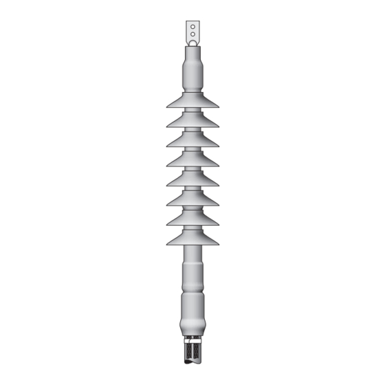
Cold Shrink Silicone Rubber
Termination QT-III
7672-S-8-TS
Instructions
IEEE Std. No. 48-1996
Class 1 Termination
69 kV Class 350 kV BIL
IEC 60840
72,5 kV
Kit Contents:
1 Silicone Rubber Lug Seal Insulator Assembly
1 Hi-K Stress Control Assembly
1 Silicone Rubber Insulator Assembly
1 Silicone Rubber Skirted Insulator Assembly
1 Pre-formed Ground Braid Assembly
3 Constant Force Springs
1 Roll Scotch
®
Electrical Shielding Tape 24
6 Tubes P55/R Red Compound (Non-Silicone Grease)
1 Roll Scotch
®
Sealing Mastic 2229, 1" (25 mm) wide
8 Strips Hi-K Mastic (1-6" × 22", 7-2" × 11")
1 Roll Scotch
®
Silicone Rubber Tape 70
Vinyl Electrical Tape Super 88, 1½" × 44'
1 Roll Scotch
®
1 6" (150 mm) Hi-K Mastic Pad
1 3M
Cable Cleaning Pads CC-3
™
1 Copper Foil Tape Strip 1181, 15" long
4 Instruction Sheets
Note: Do not use knives to open plastic bags.
Kit Number
7672-S-8
Primary Insulation
O.D. Range
1.94"–3.08"
(49.3–75.4 mm)
Table 1
mCAUTION
Jacket O.D. Range
2.45"–3.35"
(62.2–85.1 mm)
3M
Cold Shrink Silicone Rubber
™
Skirted Termination Kit QT-III
for Tape Shielded Cable
7672-S-8-TS
78-8126-9537-3-B
Working around energized systems may cause serious injury or
death. Installation should be performed by personnel familiar with
good safety practice in handling electrical equipment. De-energize
and ground all electrical systems before installing product.
Conductor Size Range
AWG (mm
)
2
250–1750
(120–850)
Advertisement

Related Manuals for 3M QT-III


Summary of Contents for 3M QT-III
- Page 1 (49.3–75.4 mm) (62.2–85.1 mm) (120–850) Table 1 Cold Shrink Silicone Rubber ™ Skirted Termination Kit QT-III for Tape Shielded Cable 7672-S-8-TS 78-8126-9537-3-B mCAUTION Working around energized systems may cause serious injury or death. Installation should be performed by personnel familiar with good safety practice in handling electrical equipment.
- Page 2 Correct Installation of Termination 78-8126-9537-3-B...
-
Page 3: Prepare Cable
Note: Check to insure all of the 3M™ Termination Assemblies QT-III will fit over the lug. If the lug will not fit through the assembly cores, this termination can not be installed using this lug. Do not remove any of the cores at this time. - Page 4 2.0 Install Ground Braid Assembly 2.1 Select the pre-formed ground braid assembly from the kit. Pass the end of the cable through the ground braid assembly loop, and position the ground braid assembly around the tape shield shown. (Figure 2) Figure 2 2.2 Select the 3 constant force springs from the kit.
- Page 5 2.4 Secure the two tails of the ground braid assembly to the cable jacket approximately 6 inches (150 mm) from the cable jacket edge with several wraps of vinyl tape. (Figure 4) Figure 4 Cut four 1" (25 mm) lengths of 1" ( 25 mm) wide Scotch® Sealing Mastic 2229 . Remove the release liner and roll each mastic strip into a small roll.
- Page 6 2.6 Select the roll of 1" (25 mm) wide Scotch® Sealing Mastic 2229 from the kit and cut a length of the mastic. Using light tension, apply a single wrap of mastic around the cable jacket over the ground braid solder blocks and the previously applied mastic.
- Page 7 3.1 Check to be sure the cable fits within the kit ranges as shown in Table 1. 3.2 Position lug/connector and crimp according to manufacturer’s directions. Remove excess oxide inhibitor and sharp crimp flashing following crimping. Refer to page 14 for 3M lug/connector crimping information up to 1000 kcmil.
- Page 8 5.0 Install Termination 5.1 Select the large hi-K mastic pad from the kit. Remove the liners and align the pad with 1" (25 mm) covering the semi-con, and 5" (127 mm) covering the cable insulation. Using light tension, wrap the pad around the cable insulation two times.
- Page 9 5.3 Starting 5" (127 mm) from the cut end of the insulation, apply 2 tubes of P55/R Red Compund (non-silicone grease) over exposed insulation and vinyl tape-wrapped mastic pad. (Figure 11) Figure 11 5.4 Select the Stress Control Assembly (medium length tubular assembly on white core) from the kit. Slide the Stress Control Assembly over the lug and cable with the loose core end toward the lug.
- Page 10 5.6 Wrap two half-lapped layers of highly-tensioned Scotch® Vinyl Electrical Tape Super 88 over the hi-K mastic, leaving approximately 0.125" (3 mm) of mastic exposed at each end. Taper the exposed edges of the hi-K mastic onto the cable by gently pressing along the edge with your finger. (Figure 14) Figure 14 5.7 Select one or more of the 2"...
- Page 11 5.9 Apply additional wrap(s) of hi-K mastic (not folded) onto the cable insulation for 1" (25 mm) and taper the hi- K mastic 2" (50 mm) onto the lug barrel. (Figure 17) When using a tapered barrel lug, extend the hi-K mastic onto the barrel 2"...
- Page 12 5.12 Select the Silicone Rubber Lug Seal Insulator from the kit. Slide the lug seal insulator onto the cable insulation with the loose core end toward the cable insulation. Position the lug seal insulator tube (not the core) 2" (50 mm) onto the lug barrel.
- Page 13 5.14 Select the Silicone Insulator Assembly (long tubular assembly) from the kit. Slide the Silicone Insulator Assembly over the lug and cable with the loose core end toward the cable jacket. Overlap the lug seal insulator, and align the Silicone Insulator Assembly Tube (not the core) with the end of the lug seal. Remove the core by pulling the loose end while unwinding counter-clockwise.
- Page 14 Warranty; Limited Remedy; Limited Liability. This product will be free from defects in material and manufacture for a period of one (1) year from the time of purchase. 3M MAKES NO OTHER WARRANTIES INCLUDING, BUT NOT LIMITED TO, ANY IMPLIED WARRANTY OF MERCHANTABILITY OR FITNESS FOR A PARTICULAR PURPOSE.
Need help?
Do you have a question about the QT-III and is the answer not in the manual?
Questions and answers