
Related Manuals for AIC TB101-HA


Summary of Contents for AIC TB101-HA
- Page 1 TB101-HA NEBS/Telco Ready Barebone User Manual P/N: H881BD0W41-00000-0 Document Number: MAN-00107-A ...
-
Page 2: Table Of Contents
Chapter 1. Product Introduction ..........5 1.1. General Information .............. 5 1.2. System Specifications ............6 1.3. Front View of TB101-HA ............8 1.4. Rear View of TB101-HA ............8 1.5. Top View of TB101-HA ............9 Chapter 2. Hardware Setup ............10 2.1. - Page 3 Updating BMC Firmware ............ 36 Chapter 6. Technical Support ..........37 Copyright © 2012 AIC, Inc. All Rights Reserved. This document contains proprietary information about AIC products and is not to be disclosed or used except in accordance with applicable agreements.
-
Page 4: Safety Information
Safety Information When installing, operating, or performing maintenance on this equipment, basic safety precautions, as listed below, should always be followed to reduce the risk of fire, electric shock, and personal injuries. Read and understand all instructions. Observe warnings and instructions marked on the product. ... -
Page 5: About This User Manual
About This User Manual TB101-HA This document provides a detailed description of the including: General Features of the Product Hardware Setup Motherboard Settings BIOS Configuration and Settings BMC Configuration and Settings ... -
Page 6: Chapter 1. Product Introduction
Chapter 1. Product Introduction 1.1. General Information TB101-HA, a 1U NEBS/Telco Ready Barebone, Dual Socket B2 (LGA1356) to support 2 x Intel Xeon processor E5-2400 series. TB101-HA has 2 x 2.5” external HDD bays for ® ® flexible storage applications. TB101-HA harnesses MAX I/O™ technology to maximize the usage of off-the-shelf expansion cards in the barebone. -
Page 7: System Specifications
1.2. System Specifications Dimensions (with chassis ears/protrusions) mm : 482.6 x 541.8 x 44.4 W x D x H inches : 19 x 21.3 x 1.75 Motherboard Motherboard Hadar (PSG-M-HADPPATS-102) Processor Dual LGA1356 (Socket-B2) to support 2 x Intel Xeon processor E5-2400 series ®... - Page 8 On-Board Devices Built-in SAS controller with RAID support on Intel® C600 series chipset • 2 x mini-SAS connectors (4 SAS ports per mini-SAS) Built-in controller with RAID support on Intel® C600 series chipset SATA • 2 x SATA2 ports (SATA1, SATA2) •...
-
Page 9: Front View Of Tb101-Ha
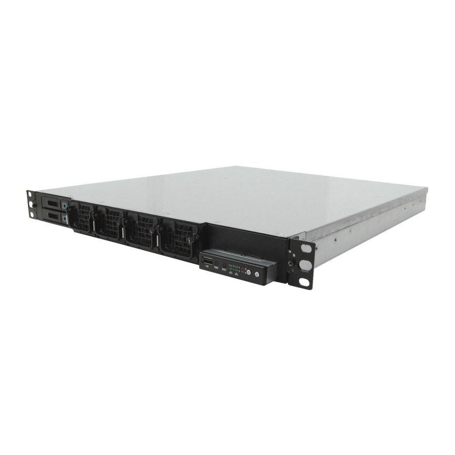
1.3 Front View of TB101-HA Front view with front door Front view without front door 4 Hot-Swap Redundant fans 2 x 2.5” HDD Icon Color Controls Icon System Behavior System Behavior Solid: System On Power LED Green Power ON/OFF Push for Power On or Off... -
Page 10: Top View Of Tb101-Ha
1.5. Top View of TB101-HA The barebone server includes the basic components shown as below. 4 Hot-Swap Redundant fans Hot-swap HDD Trays Fan Duct Hadar MB AC/DC650W 1+1 Rear IO Expansion Slot Hot-Swap Redundant PSU... -
Page 11: Chapter 2. Hardware Setup
Chapter 2. Hardware Setup This section demonstrates maintenance procedures in replacing a defective part once the TB101-HA appliance is installed and is operational. 2.1. Chassis Cover 2.1.1 Removing the Chassis Cover 1. Release screws from the upper panel and rear panel. - Page 12 2.1.3 Installing the CPU 1. Press the load lever to release the load plate. Load lever 2. Lift the load plate. Load plate 3. Remove the processor protective cover from CPU socket. Processor protective cover 4. Align the processor cutouts against the socket notches. Cutouts 5.
- Page 13 the load plate & load lever. Press to close 2.1.4 Installing the CPU Heatsink To install the CPU heatsink: Position the heatsink on the CPU, and fasten the four screws attaching the heatsink to the motherboard. 2. Tighten the four screws in a diagonal sequence, a couple of turns at a time, until all four screws are secure and the heatsink is securely fastened to the chassis.
-
Page 14: System Memory
2.2. System Memory This server board supports twelve DDR3 DIMM slots. 1. Populate DIMMs in the following order: DIMM DIMM arrangement Numbers 2 DIMMs CPU0 DIMM 0 CPU1 DIMM 0 4 DIMMs CPU0 DIMM 0 CPU0 DIMM 0 CPU1 DIMM 0 CPU1 DIMM 0 6 DIMMs CPU0 DIMM 0... - Page 15 DIMM DIMM arrangement Numbers CPU0 DIMM 0 8 DIMMs CPU0 DIMM 0 CPU0 DIMM 0 DIMM 1 CPU1 DIMM 0 CPU1 DIMM 0 CPU1 DIMM 0 DIMM 1 CPU0 DIMM 0 CPU0 DIMM 0 10 DIMMs CPU0 DIMM 0 DIMM 1 DIMM 1 CPU1 DIMM 0 CPU1 DIMM 0...
-
Page 16: Drive Bays
2.3. Drive Bays 2.3.1 Installing or replacing 2.5" hot-swap SAS/SATA/SSD drive bays 1. Remove the front cover by releasing two screws from each side. 2. Release a drive tray by pushing the release button to open the latch. 3. Firmly hold the tray latch and pull the drive out of the drive slot. ... - Page 17 Slide the drive into the drive slot until it is fully seated. Make sure the drive tray is correctly secured in place when its front edge aligns with the bay edge. Close the latch until it clicks to lock the drive. Repeat steps from1 to 5 to install the rest of the HDDs.
-
Page 18: Riser Card
2.4. Riser Card RISER CARD PN (PSG CODE) DESCRIPTION PSG-RC-HA1U-40-101 (PSG Code: PE1U16) Max IO supports 1 x PCIe X16, 2 x PCIe X8,1 x PCIe X4 RISER CARD DIAGRAM Top view (Add-on card side) PCIE6 (X16) PCIE4 (X8) Buttom view (side) Slot Bandwidth PCIE 4 (PCIE -16X) PCIE 6 (PCIE -16X) -
Page 19: Expansion Slot
2.5. Expansion Slot 2.5.1 Installing an External Expansion Card to the Riser Card 1. Remove two screws to release the bracket. 2. Install the expansion card on the proper slot and connect it to the riser card. Secure the bracket to fix the expansion card. -
Page 20: System Fans
2.6. System Fans 2.6.1 Removing or Replacing the System Fans Hold the fan lever firmly and pull the fan out of the server chassis to remove the fan module from the server chassis. 2.7. Power Supply 2.7.1 Removing or Replacing the Power Supply Module Release two thumb screws from PSU module. -
Page 21: Chapter 3. Motherboard Settings
Chapter 3. Motherboard Settings This section describes the jumpers, internal connectors, and internal LEDs setting on Hadar (PSG-M-HADPPATS-102) motherboard. Motherboard layout and important jumper settings of the system will be listed as below. 3.1. Motherboard Layout 3.2. Motherboard Content List Connectors Location Connectors... - Page 22 3.2.1 Internal Connectors/Jumpers Jumpers Description 1. SCOM2_T3OUT 2. SCOM2_R4IN BMC debug Port 3. GND 1. GND 2. DACROA 3. DACGOA 4. NC 5. DDC_DATAO 6. GND 7. GND 8. DACBOA 9. NC 10. AHSYNCO 11. AVSYNCO 12. DVO_5V 13. GND 14.
- Page 23 1.USB5V 2.USB5V 3.USBD- 4.USBD- 5.USBD+ 6.USBD+ J13 / J16 7.GND 8.GND 9.GND 10.NC 1.GND 2. GPIOB0 GPIO 3. BMC_GPIOE5 4. BMC_GPIOJ1 5. GPIOB7 6. BMC_GPIOJ0 A1. GND B1. PWR_BTN A2. GND B2. RST_BTN A3. GND B3. NMI_BTN A4. GND B4. UID_BTN A5.
- Page 24 ME Recovery Mode Default: NC (Jumper) 1.GND 2.CLK_33M 3. SUS_STAT_N 4.ICH_LPC_LFRAME 5. AST_SERIRQ 6. RST_PLTRST_N LPC Debug Port 7. ICH_LPC_LAD2 8.ICH_LPC_LAD3 9. ICH_LPC_LAD1 10.+3.3V 11.GND 12.ICH_LPC_LAD0 1. P3V3_VBAT Clear CMOS 2. RST_RTCRST (Jumper) 3.GND Default (1-2 close) 1.GND 5. +12V 2.
- Page 25 3.2.2 Internal LEDs 1. Rear Panel LED Definition Status Description Green JRJ45 NIC1 activity detected (Blinking) (Upper Right) NIC1 is not active, LAN cable no connect JRJ45 Status LED 1G : Orange, 100M: Green 10M/No connect: Off (Upper Left) Green JRJ45 NIC2 activity detected (Blinking)
-
Page 26: Chapter 4. Bios Configuration And Settings
Chapter 4. BIOS Configuration and Settings 4.1. BIOS Setting 1. Press DEL to run the setup procedure. 2. There will be a message “Entering SETUP” displayed on the diagnostics screen. - Page 27 3. Identify the BIOS Version 4. Load Optimal Default setting 5. Save the setting and exit BIOS setup utility.
-
Page 28: Updating Bios
4.2. Updating BIOS Important Notes: 1. To identify the current BIOS version, please examine BIOS setup. HADRV070 can only be upgraded from HADRV050 or later version. There are two methods to update the latest BIOS. 1. Update by Messiash Flash utility during POST 2. - Page 29 Update by AMI AFUDOS utility under DOS environment If you need to update Flash in the DOS environment, please use AFUDOS utility. To use this utility, you must include the flash.bat, AICFLASH.EXE, AFUDOS.exe, and bin file in the same folder. Please follow the instructions to update whole flash part: 1.
-
Page 30: Chapter 5. Bmc Configuration And Settings
Chapter 5. BMC Configuration and Settings Insert Ethernet LAN cable into the BMC LAN port. There are two methods to setup BMC IP: BMC management port 5.1. Method 1 (Use the BIOS setup) 1. BIOS SETUP Server Mgmt BMC network configuration Configuration Address source ... - Page 31 2. Input IP address. Set static IP. 3. Input subnet mask address.
-
Page 32: Method 2 (Use A Dos Tool - Syscheck)
5.2. Method 2 (Use a Dos tool - Syscheck) 1. Type : sc –lanset. 2. Modify IP setting. 3. Input IP address. - Page 33 4. Input submask address. Below IP address is an example using a default IP setting. User is allowed to change the IP address for realistic use. 5. Finish BMC IP configuration.
-
Page 34: Connect To Bmc
5.3. Connect to BMC Below IP address is an example using default IP setting. User is allowed to change the IP address for realistic use. 1. Open the browser then type default BMC IP address: 192.168.22.22 2. Use the default user name and password for first-time login to ASTER. Field: Default UserName:... - Page 35 3. Information of firmware 4. Server Health - Sensor Readings: 5. Configuration Please refer to AIC BMC User Guide for more information on AIC BMC.
- Page 36 Mouse Mode setting: For Windows OS environment, set mode to absolute. For Linux OS environment, set mode to relative. Remote Control: Environmental setting:...
-
Page 37: Updating Bmc Firmware
3. Execute a.bat batch file to update the BMC firmware Example: A:>cd SB301C01 A:\ SB301C01>a.bat This is just an example. The latest BMC firmware version is available from the FAE or AIC website. After update BMC firmware, please power off and then power on system. -
Page 38: Chapter 6. Technical Support
Chapter 6. Technical Support Http://www.aicipc.com TAIWAN Tel: +886.3.313.8386 Fax: +886.3.313.8377 Email Technical Support: support@aicipc.com JAPAN Tel: +81.43.202.8380 Fax: +81.43.202.8381 Email Technical Support: support@aicipc.com CHINA Tel: +021.54961421, +021.54961422 Fax: Extension: 608 Email Technical Support: support@aicipc.com AMERICA - West coast ... - Page 39 Note...
Need help?
Do you have a question about the TB101-HA and is the answer not in the manual?
Questions and answers