Advertisement
Quick Links
SFAB
Flow sensor
Instructions | Operating
8110112
201904c
[8110114]
Translation of the original instructions
1
About this document
1.1
Applicable documents
All available documents for the product è www.festo.com/pk.
2
Safety
2.1
General safety instructions
–
Only use the product in original status without unauthorised modifications.
–
Only use the product if it is in perfect technical condition.
–
Observe labelling on the product.
–
Condensation, oil mist, foreign matter and other impurities in the compressed
air can damage the product. Only use media in accordance with the specifica
tions è Technical data.
–
Comply with specified critical limits.
–
Take into consideration the ambient conditions at the location of use.
–
The product is suitable for industrial purposes only. Measures for radio inter
ference suppression may be necessary in residential areas.
Return to Festo
Hazardous substances can endanger the health and safety of personnel and
cause damage to the environment. To prevent hazards, the product should only
be returned upon explicit request by Festo.
–
Consult your regional Festo contact.
–
Complete the declaration of contamination and attach it to the outside of the
packaging.
–
Comply with all legal requirements for the handling of hazardous substances
and the transport of dangerous goods.
2.2
Intended use
The SFAB is designed to monitor changes in the flow rate and air consumption of
gaseous media in piping systems or terminals in industry.
2.3
Training of qualified personnel
–
Installation, commissioning, maintenance and disassembly should only be
conducted by qualified personnel.
3
Further information
–
Accessories è www.festo.com/catalogue.
–
Spare parts è www.festo.com/spareparts.
4
Service
Contact your regional Festo contact person if you have technical questions
è www.festo.com.
5
5.1
Festo AG & Co. KG
Ruiter Straße 82
73734 Esslingen
Germany
+49 711 3470
www.festo.com
8110112
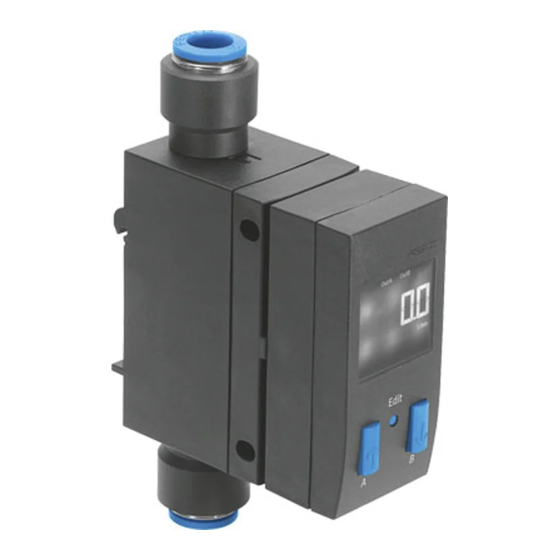
1 Supply port 1
2 Display
3 B pushbutton
4 Edit button
5 A pushbutton
Fig. 1 SFAB
6
6.1
The SFAB uses a thermal measurement method. Here, the amount of heat drawn
from a heated surface of the sensor by the medium flowing past it is calculated.
Through the amount of heat removed, the flow rate or accumulated air consump
tion is determined and shown on the display. The connection to higherlevel sys
tems is implemented through 2 binary outputs (Out A/OutB) and one analogue
output. Switching points can be defined for both binary outputs. Switching points
for both binary outputs are possible for flow rate measurement, a consumption
switching pulse for output A (OutA) is possible for cumulative air consumption
measurement. The combination of cumulative air consumption measurement
(OutA) and flow rate measurement (OutB) is possible. The flow value is output via
the analogue output.
7
7.1
Fig. 2 Mounting on Hrail
1. Maintain lateral distance x = 10 mm to earthed surfaces.
2. Hang SFAB in Hrail.
3. Press SFAB in the direction of the arrow.
Ä SFAB snaps into place.
Product description
Product design
Function and application
Functional principle
Assembly
H-rail (manifold assembly)
6 Plug for the electrical connection
(M12)
7 Hole for plate mounting
8 Supply port 2
9 Mounting slide for Hrail and wall
mounting (rear)
Advertisement

Related Manuals for Festo SFAB


Summary of Contents for Festo SFAB
- Page 1 (OutA) and flow rate measurement (OutB) is possible. The flow value is output via Intended use the analogue output. The SFAB is designed to monitor changes in the flow rate and air consumption of gaseous media in piping systems or terminals in industry. Assembly...
- Page 2 1. Maintain lateral distance x = mm to earthed surfaces. +24 V +24 V 2. Fasten the adapter plate with 2 screws M3. 3. Hang the SFAB in the adapter plate. 4. Press SFAB in the direction of the arrow. Ä SFAB snaps into place. PNP/NPN PNP/NPN Plate mounting...
-
Page 3: Preparing Commissioning
Security code active (lock blocked against unauthorised program ming) Security code inactive (lock) Press key (here A key). Press the A key or B key. SFAB changes to the setting indicated by the Tab. 5 Consumption switching pulses arrows. Display components Press A and B pushbuttons simultaneously. - Page 4 12. Select the switching element function (NO/NC) with the A/B pushbuttons. 13. Press the Edit button to confirm the set value. Ä SFAB is in RUN mode. 14. Check whether the SFAB switches as desired with a test run (vary the flow rate). 9.7.2.2...
- Page 5 In order to detect the system status over longer distances, a colour change can be set at the OutB output. If the set switching threshold is exceeded or not reached, For the types SFAB600U and SFAB1000U, the unit l/h cannot be set due to dis the colour of the display changes.
- Page 6 To reset a measure value to zero, press the B pushbutton in RECORDER mode. Operation and use Changes to the device settings take effect immediately at the outputs. The air mass flow displayed by the SFAB refers to the standard condition set in the special menu under Options. When comparing volumetric flow rates: –...
- Page 7 CE marking (declaration of conformity In accordance with EU EMC Directive Hysteresis setting range 0 %FS … 90 %FS è www.festo.com/sp) In accordance with EU RoHS Directive SFAB...EX2: in accordance with EU Explosion Protec Immissions/emissions tion Directive (ATEX) Storage temperature [°C] –20 … +80 Degree of protection...
- Page 8 Fig. 12 UL Recognized Component Mark for Canada and the United States. Only for con nection to an NEC Class 2 supply. Raccorder Uniquement a un circiut de Classe 2. Observe the following if the UL requirements are to be complied with in your application: •...
Need help?
Do you have a question about the SFAB and is the answer not in the manual?
Questions and answers