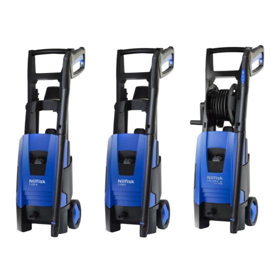
Nilfisk-Advance C 125.4 Repair Manual
Hide thumbs
Also See for C 125.4:
- Instructions for use manual (23 pages) ,
- Instructions for use manual (24 pages)
Advertisement
Advertisement

Summary of Contents for Nilfisk-Advance C 125.4
- Page 1 C 125.4 C 130.2 C-PG 130.2 X-TRA Repair Manual...
-
Page 2: Table Of Contents
Index A. Safety precautions B. Technical data C. Construction Service / Repair 7-11 E. Torque 14-15 F. Operating supplies G. Operation 17-19 H. Diagram... -
Page 3: Safety Precautions
Safety precautions. WARNING! High pressure jets can be dangerous. Never direct the water jet at persons pets, live electrical equipment or the machine self. The operator and anyone in the immediate vicinity of the site of cleaning should take action to protect themselves from being struck by debris dis- lodged during operation. -
Page 4: Technical Data
Technical Data. C125.4 C130.2/C-PG 130.2 Product segment: Consumer Specification Max 125 Max 130 Voltage Frequency Power consumption Power absorbed Numbers of revolutions 17500-18000 17000-18000 rpm./ min. Water volume, HP l / min. 5,3-6,3 5,3-6,3 Pump pressure 85-100 90-105 Nozzle pressure 79-94 84-99 Opening pressure... -
Page 5: Construction
Construction. C 125.4 - C 130.2 - C-PG 130.2 X-TRA Construction of cabinet parts. (!) Part 24, 25, 26 are on only used on PG versions... - Page 6 Construction. C 125.4 - C 130.2 - C-PG 130.2 X-TRA Construction of pump unit.
-
Page 7: Service / Repair
Service / Repair. Dismounting / mounting of front cabinet and accessory storage. Tools: Torx 20 screwdriver and flat screw driver Remove the handle by pressing the 2 * 2 snap locks (fig.2). Loosen one side first and then the other side. Remove the 2 torx (TX20) screws from the rear side (fig. - Page 8 Service / Repair. Dismounting / mounting of Control Unit and/or Wireless Unit (Only PG version). Tools: Torx 9 screwdriver Controle Unit: Disconnect cable to Wireless Unit, Remove the 3 torx (T9) screws , ex- change Controle Unit, dismount the 3 wires. Mount and tighten the torx (TX9) screws Torque: max 0,8 Nm, and connect cable to Wire- less Unit, check the circuit diagram and mount the 3 wires accordingly on the Control Unit Wireless Unit: Disconnect cable to Wireless Unit, slide the Wireless Unit out, exchange...
- Page 9 Service / Repair. Pairing of the machine and the PowerGrip handle (Only PG version). Pairing of the wireless devices is needed if: the PowerGrip has been exchanged the Wireless Unit in the PowerGrip has been exchanged the Control Unit in the machine has been exchanged ...
- Page 10 Service / Repair. Dismount / mounting of motor cover. Place the cleaner on the side and remove the 5 torx 20 screws. Fig 1 Remove the wheel to remove the 5th. Screw if the torx screw dirver is too short. Fig 2 Now the cabinet can be removed and the motor / pump unit can be taken out.
- Page 11 Service / Repair. Dismounting / mounting of the start / stop valve. Fig 1 is showing how the start / stop valve must be assembled. A special tool is needed in order to take out the seat of the start / stop valve (fig 2) Please use “Puller for valve seat M4”...
- Page 12 Service / Repair. Dismounting / mounting of water / oil seal and valves. To change the oil seals, water seals and pressure valve, use a screw driver to dismount the parts (fig 3 & 4). Alternatively there is a puller number 1220103 to pull out the valves seats (pressure and suction valves.
- Page 13 Service / Repair. IMPORTANT mounting information: In order to optimize the self suction mode the valve bodies must be positioned correct ac- cording to the water canals inside the cylinder head. The “leg” of the valve body must not be placed in front of a canal.
-
Page 14: Torque
Torque. Pump torque. - Page 15 Torque. Cabinet torque.
-
Page 16: Operating Supplies
Operating supplies Recommended oil types: The pump is filled with 80 ml LHM 32 from the production. In case of service where the oil must be changed Nilfisk- Advance recommends to use 80 ml Bartran HV 46. Alternative oil types that are allowed: BP, Bartram HV 46 Shell, Tellus T 46 Exxon, Statoil Univis N 46... -
Page 17: Operation
Operation. 3.0 Start stop System guide 3.1 No pressure in system No pressure in system - except inlet pressure 3 bar. Machine switch off. Pump 3 BAR Non return valve 3 BAR Inlet Outlet 3 BAR 3.2 Start up-pressure build up Machine switch on / Start up –... - Page 18 Operation. 3.3 Pressure build up-opening pressure / close gun Gun close. Pressure build up. Opening pressure. Micro switch is activated Pump 130 BAR Non return valve Inlet 3 BAR Outlet 130 BAR 3.4 Motor stop – Standby pressure Gun close. Motor stops. Pressure in hose decreases to standby pressure. Pump pressure is also standby pressure.
- Page 19 Operation. 3.5 Gun is activated Gun is open - Control piston is closed. Micro switch is deactivated. Motor starts. Pump 3 BAR Non return valve 3 BAR Inlet Outlet 3 BAR 3.6 Machine run Machine runs (normal working pressure). Gun is open. Pump 100 BAR Non return valve...
-
Page 20: Diagram
Wiring Diagram Wiring Diagram C 125.4 - C 130.2... - Page 21 Wiring Diagram Wiring Diagram C-PG 130.2 X-TRA...


Need help?
Do you have a question about the C 125.4 and is the answer not in the manual?
Questions and answers