Advertisement
Quick Links
Advertisement

Related Manuals for Nilfisk-Advance C 120.4


Summary of Contents for Nilfisk-Advance C 120.4
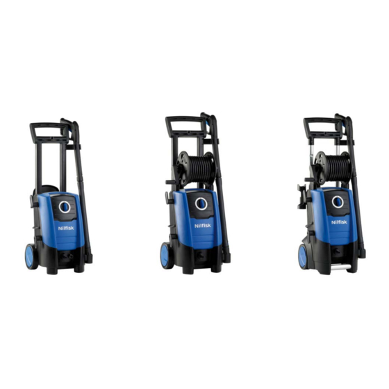
- Page 1 C 120.4 - C 120.4 X-Tra E 130.2 - E 130.2 X-Tra E 140.2 - E 140.2 X-Tra Repair Manual...
- Page 2 Index A. Saftey Issues B. Technical data C. Construction Service /Repair 10-18 E. Operation. 19-28 F. Diagram 29-30...
- Page 3 Safety Issues. Safety precautions • WARNING! High pressure jets can be dangerous. Never direct the water jet at persons pets, live electrical equipment or the machine self. • The operator and anyone in the immediate vicinity of the site of cleaning should take action to protect themselves from being struck by debris dis- lodged during operation.
- Page 4 Technical Data. Product segment: Consu- C 120.4 X-tra E 130.2 X-tra E 140.2 X-tra Specification Voltage Frequency Power consumption Power absorbed Numbers of revolutions rpm./ min. 2800 2800 2800 Water volume, HP l / min. Pump pressure Nozzle pressure Opening pressure Retaining time min.
- Page 5 Construction. C 120.4 Construction of cabinet parts.
- Page 6 Construction. E 130.2 X-tra - E 140.2 X-tra Construction of hose reel.
- Page 7 Construction. E 130.2 - E 140.2 Construction of cabinet parts...
- Page 8 Construction. C 120.4 E 130.2 E 140.2 Construction of motor pump unit.
- Page 9 Construction. C 120.4 X-tra - E 130.2 X-tra - E 140.2 X-tra Construction of motor pump unit.
- Page 10 Service / Repair. Dismounting / mounting of front cabinet and front chassis. Remove 4 torx Screws (TX 20 )(fig.1) and then 2 torx Screws (fig.2).Then use a small screwdriver to tip out the cabinet. (fig.3).Remove 6 torx screws in the front chassis (fig.4) and 2 screws at the bottom (fig.5) Fig.1 Fig.2...
- Page 11 Service / Repair. Dismount / Mounting of Motor cover. Remove 4 torx (TX20) screws . (fig.1 ) When mounting the motor cover and front chassis be sure that the wire are in the right position. (fig.2 and 3) Fig.1 Fig.2 Fig.3...
- Page 12 Service / Repair. Dismounting / Mounting of S/S valve. Remove micro switch box carefully with 2 screw driver ( fig.1) and then the S/S valve (fig.2.) Mount the micro switch (fig.3) and press down the micro switch arm with a screwdriver (fig 4). Fig.1 Fig.2 Fig.4...
- Page 13 Service / Repair. Dismounting / mounting of oil seal. Tip up the oil seal with a screwdriver and discard (fig.1). Clean up and lubricate. Mount a new oil seal. Fig.1...
- Page 14 Service / Repair. Dismounting / mounting of suction and pressure valves. Remove valve seat with tool and discard them (fig.1 and 2). Mount new valves with a slight finger pressure and special tool no.1220103 (fig 3 and 4). Clean up and lubricate before mounting. Fig.3 Fig.2 Fig.3...
- Page 15 Service / Repair. Fig.1 Bearing track on fig.1 and fig 2 are different. (inner diameter are different) Bee sure it fits to the. wobble disc. Fig.2 Wobble Disc marking and assembling 120 bar ”1-1” or ”6,6°-1” 130-140 bar ”2-1” or ”7,5°-1” Fig.3...
- Page 16 Service / Repair. Dismounting / Mounting of Easy start valve. Remove the easy seat with a small hook (fig.1) then remove the o-ring underneath the seat ,with a small screwdriver . Mounting : place the ball on the end of the spring (fig.2), be sure the the ball are in the right position when mounting plug.
- Page 17 Service / Repair. Torque.
- Page 18 Nilfisk Service / Repair. Guidance of measuring of electrical motor. 1,7 KW Motor 2,1 KW Motor 6,1 ohm. 7,1 ohm. 8,9 ohm. 8,9 ohm. 2,8 ohm. 1,8 ohm. Capacitor Plug. Power supply Plug.
- Page 19 Operation guide. In this situation the position of the parts are following: The none return valve( A) is closed by the spring (B) as there is no pressure on either of the sides. The easy start ball valve (C) is pressed against the up- per seat by the easy start spring (D) The s/s spring pressed the s/s piston, and the Activation arm (E) is taken to the front position the micro switch (F) at the “switch on”...
- Page 20 Operation guide. 1. The none return valve (A) is closed by the spring (B) as the pressure on the front side is still not high enough to open it. 2. The easy start ball valve (C) moves a little from the upper seat as the easy start spring (D) is pressed a little.
- Page 21 Operation guide. During building-up of pressure, the position of the parts are following: 1. The none return valve (A) open a little because of the high pressure from pump.2. The easy start ball valve (C) moves to the lower seat as the easy start spring (D) impressed more.
- Page 22 Operation guide. 1. The none return valve (A) is fully open because of full working pressure and flow. 2. The easy start ball valve (C) is pressed against the lower seat by the pressure from the pump. 3. The s/s spring is pressed a little , but the Activation arm (E) is still on the front po- sition, The micro switch (F) at “switch on”...
- Page 23 Operation guide. 2.5 Handle release 1. The none return valve (A) is closed by the pressure in the hose system. 2. The s/s spring is pressed at max position, the Activation arm (E) moves back , presses the Micro switch (F) at “switch off” position (means that the motor (G) is stopped).
- Page 24 Operation guide.
- Page 25 Operation guide.
- Page 26 Operation guide.
- Page 27 Operation guide.
- Page 28 Operation guide.
- Page 29 Wiring Diagram. Circuit Diagram...
- Page 30 Wiring Diagram Wiring Diagram...
Need help?
Do you have a question about the C 120.4 and is the answer not in the manual?
Questions and answers