Nordson Encore HD Customer Product Manual
Manual powder spray gun
Hide thumbs
Also See for Encore HD:
- Customer product manual (273 pages) ,
- Manual (98 pages) ,
- Product manual (68 pages)
Table of Contents
Advertisement
Quick Links
r
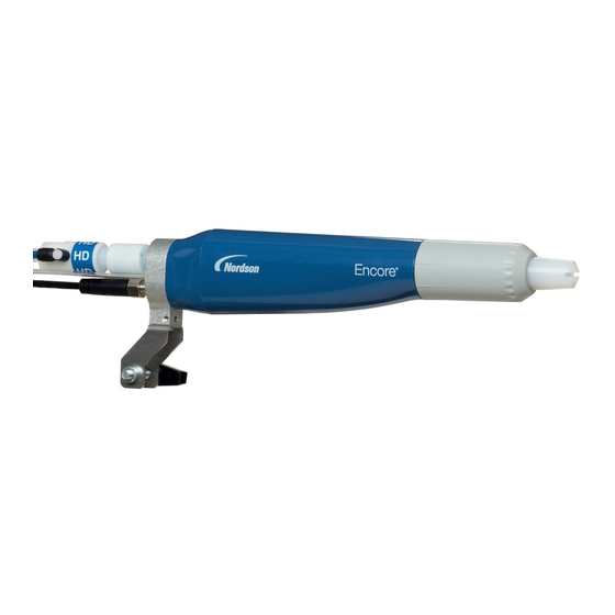
Encore
HD
Manual Powder Spray Gun
Customer Product Manual
Part 1604869-13
Issued 09/19
For parts and technical support, call the
Industrial Coating Systems Customer Support Center
at (800) 433-9319 or contact your local Nordson representative.
This document is subject to change without notice.
Check http://emanuals.nordson.com/finishing for the latest version
and available local languages.
NORDSON CORPORATION • AMHERST, OHIO • USA
Advertisement
Table of Contents

Subscribe to Our Youtube Channel
Related Manuals for Nordson Encore HD


Summary of Contents for Nordson Encore HD
- Page 1 Issued 09/19 For parts and technical support, call the Industrial Coating Systems Customer Support Center at (800) 433-9319 or contact your local Nordson representative. This document is subject to change without notice. Check http://emanuals.nordson.com/finishing for the latest version and available local languages.
- Page 2 Contact Us Notice This is a Nordson Corporation publication which is protected by copyright. Nordson Corporation welcomes requests for information, comments, and Original copyright date 2014. No part of this document may be inquiries about its products. General information about Nordson can be...
- Page 3 03/18 Changed description for gun labels 07/18 Added nLighten LED inspection kit, added XD electrode support, new reference document links and updated description for part number 1600819. Added power supply resistance test nomenclature changes Part 1604869-13 E 2018 Nordson Corporation...
- Page 4 Change Record Part 1604869-13 E 2018 Nordson Corporation...
-
Page 5: Table Of Contents
....... . . Maintenance Procedures ....... Part 1604869-13 E 2018 Nordson Corporation... - Page 6 7-11 Powder Hose and Air Tubing ......7-11 Part 1604869-13 E 2018 Nordson Corporation...
-
Page 7: Safety
Regulations and Approvals Make sure all equipment is rated and approved for the environment in which it is used. Any approvals obtained for Nordson equipment will be voided if instructions for installation, operation, and service are not followed. All phases of equipment installation must comply with all federal, state, and local codes. -
Page 8: Personal Safety
Clean, maintain, test, and repair equipment according to the instructions in your equipment documentation. Use only replacement parts that are designed for use with original equipment. Contact your Nordson representative for parts information and advice. Part 1604869-13 E 2018 Nordson Corporation... -
Page 9: Grounding
Disconnect and lock out electrical power. Close pneumatic shutoff valves and relieve pressures. Identify the reason for the malfunction and correct it before restarting the equipment. Disposal Dispose of equipment and materials used in operation and servicing according to local codes. Part 1604869-13 E 2018 Nordson Corporation... - Page 10 Safety Part 1604869-13 E 2018 Nordson Corporation...
-
Page 11: Description
HD manual powder spray gun with 6 meter power cable and tubing. The Encore HD manual powder spray gun should be used with the Encore HD manual controller, which provides electrostatic voltage control, electrode air-wash air, and powder pump air. It is compatible with the following... -
Page 12: Specifications
Description Optional equipment is available for the Encore HD manual spray gun including the following: Additional flat, conical and cross-cut nozzles options 6-meter cable extension 150 and 300-mm lance extensions Pattern adjuster for use with lance extensions Ion collector See Options section beginning on page 7-4 for information on additional options. -
Page 13: Setup
Delivery In 6 mm Pattern Air 4 mm Clear Air Wash 6 mm In Gun Cable Delivery Manual Powder Hose System Controller Network/Power Interconnect Pump Control Unit Figure 3-1 System Diagram (Common System Equipment Shown) Part 1604869-13 E 2018 Nordson Corporation... -
Page 14: Spray Gun Installation
4. Connect the gun cable (6) to the gun connection on the back of the Encore HD manual system controller. 5. Use the sections of black spiral wrap supplied with the system to bundle together the spray gun cable, all air tubing, and powder hose. Take care not to smash, squish, kink, bind, or deform the powder tubing. -
Page 15: Operation
European Union, ATEX, Special Conditions for Safe Use 1. The Encore HD manual applicator shall only be used with the associated Encore XT/HD interface control unit and Encore HD controller power unit, over the ambient temperature range of +15 _C to +40 _C. -
Page 16: System Operation
Operation System Operation This manual includes information on the Encore HD Manual Powder Spray Gun. Refer to appropriate system, controller and control panel manuals for information on system components. Spray Gun Operation The spray gun interface and settings trigger allow you to change the preset or the powder flow settings, or purge the gun as needed, without using the controller interface. -
Page 17: Changing Powder Flow With The Settings Trigger
The purge length and frequency required will depend on the application. NOTE: The purge air only cleans the spray gun powder path. Refer to the system controller manual for additional HDLV purge information. Part 1604869-13 E 2018 Nordson Corporation... -
Page 18: Electrode Air Wash Operation
Standby Button Use the Standby button on the Encore HD controller to shut off the interface and disable the spray gun during breaks in production. When the controller interface is off the spray gun cannot be triggered, and the spray gun interface is disabled. -
Page 19: Changing Flat Spray Nozzles
NOTE: To clean nozzles, use the Recommended Cleaning Procedure for Powder Contact Parts on page 4-9. Nozzle Nut Flat Spray Electrode Assembly Flat Spray Nozzle Figure 4-4 Changing a Flat Spray Nozzle Electrode Assembly Bridge Figure 4-5 Correct Nozzle Orientation Part 1604869-13 E 2018 Nordson Corporation... -
Page 20: Converting From Flat Spray Nozzles To Conical Nozzles
Powder Contact Parts on page 4-9. Electrode Flat Spray Nozzle Flat Spray Electrode Holder Nozzle Nut Conical Spray Nozzle Conical-Spray Electrode Holder Deflector Figure 4-6 Converting from a Flat Spray Nozzle to a Conical Spray Nozzle Part 1604869-13 E 2018 Nordson Corporation... -
Page 21: Changing Deflectors Or Conical Nozzles
6. Screw the nozzle nut onto the gun body clockwise until finger-tight. 7. Install a new deflector on the electrode assembly. Do not bend the electrode wire. Deflector Conical Electrode Nozzle Nut Conical Electrode Holder Nozzle Assembly Figure 4-7 Changing a Conical Nozzle Part 1604869-13 E 2018 Nordson Corporation... -
Page 22: Installing The Optional Pattern Adjuster Kit
WARNING: Before performing the following tasks, turn off the controller and disconnect system power. Relieve system air pressure and disconnect the system from its input air supply. Failure to observe this warning may result in personal injury. Part 1604869-13 E 2018 Nordson Corporation... -
Page 23: Recommended Cleaning Procedure For Powder Contact Parts
Operation Recommended Cleaning Procedure for Powder Contact Parts Nordson Corporation recommends using an ultrasonic cleaning machine and Oakiter BetaSolv emulsion cleaner to clean spray gun nozzles and powder path parts. NOTE: Do not immerse the electrode assembly in solvent. It cannot be disassembled;... - Page 24 4-10 Operation Part 1604869-13 E 2018 Nordson Corporation...
-
Page 25: Repair
7. Filter assembly 19. Cable assembly 28. Settings/purge trigger 10. Display module 19B. Power supply connector (J2) 29. Screw (handle to gun body) Note: Ground terminal (19D) must always be connected to the ground screw (16). Part 1604869-13 E 2018 Nordson Corporation... -
Page 26: Display Module Replacement
6. Gently fold the trigger switch ribbon cable and display module cable into the gun, and install the display module onto the gun. 7. Slide the hook (11) onto the display module, then install the bezel (12). 8. Install and tighten the screws (13). Part 1604869-13 E 2018 Nordson Corporation... - Page 27 (new switch) Display Module and Cable J3 Connectors Adhesive Switch Support Pad Header Figure 5-2 Display Module Replacement 10. Display module 12. Bezel A. Ground wire connector 11. Hook 13. M3 x 35 screws Part 1604869-13 E 2018 Nordson Corporation...
-
Page 28: Power Supply And Powder Path Replacement
The air wash tubing will prevent a complete separation; leave it connected unless it must be replaced. Figure 5-3 Removing the Gun Body from the Handle Part 1604869-13 E 2018 Nordson Corporation... -
Page 29: Power Supply Replacement
4. Press on the end of the power supply to ensure that the power supply contact tip is firmly seated against the brass contact inside the gun body. 5. Route the power supply harness connector through the top hole in the bulkhead. Part 1604869-13 E 2018 Nordson Corporation... -
Page 30: Powder Path Removal
NOTE: To verify proper installation, place a flashlight inside the bottom of the inlet adapter and verify the internal connections by looking through the outlet tube from the front of the powder spray gun. Part 1604869-13 E 2018 Nordson Corporation... - Page 31 Figure 5-5 Powder Path Replacement 4. Outlet tube kit 7. Filter assembly 21. M3 x 20 screws 5. Elbow 17. Ground pad 24. Inlet tube/hose adapter kit 6B. Gun body 20. Handle base 25. Handle Part 1604869-13 E 2018 Nordson Corporation...
-
Page 32: Gun Re-Assembly
6. Install the nozzle (2) on the electrode assembly, making sure the keys in the electrode assembly slide into the slots on the nozzle. 7. Install the nozzle nut (1) over the nozzle and rotate clockwise to secure. Part 1604869-13 E 2018 Nordson Corporation... -
Page 33: Cable Replacement
VIEW A VIEW B Figure 5-7 Cable Replacement 13. M3 x 35 screw 16. M3 x 6 screw 18. Retaining ring 15. Lock washer 17. Ground pad 20. Handle base 21. M3 x 20 screws Part 1604869-13 E 2018 Nordson Corporation... -
Page 34: Cable Installation
5. Remove the spray trigger (27), actuator (26), and purge trigger (28) from the handle. 6. Use a tool to pry and pull the trigger switch (14) off the handle, then pull it up and out of the handle. Part 1604869-13 E 2018 Nordson Corporation... -
Page 35: Switch Installation
6. Feed the trigger switch ribbon cable through the bottom of the bulkhead and connect the ribbon cable connector to the display module as described in Display Module Installation on page 5-2. 7. Re-assemble the gun as described in Gun Re-assembly on page 5-8. Part 1604869-13 E 2018 Nordson Corporation... - Page 36 5-12 Repair Part 1604869-13 E 2018 Nordson Corporation...
-
Page 37: Troubleshooting
These troubleshooting procedures cover only the most common problems. If you cannot solve a problem with the information given here, contact Nordson technical support at (800) 433−9319 or your local Nordson representative for help. Part 1604869-13... -
Page 38: Spray Gun Power Supply Resistance Test
C or 72 F. Allow time for the multiplier to cool to room temperature for repeatable results. 225-335 Megohms at 500 VDC J2−3 (YELLOW) J2−1 (RED) FEEDBACK J2−2 (BLACK) COMMON Figure 6-9 Power Supply Resistance Test Part 1604869-13 E 2018 Nordson Corporation... -
Page 39: Electrode Assembly Resistance Test
The resistance should be 19−21 megohms. If the resistance is out of this range replace the electrode assembly. 19−21 Megohms Figure 6-10 Electrode Assembly Resistance Test Part 1604869-13 E 2018 Nordson Corporation... -
Page 40: Gun Cable Continuity Test
(BLUE) J3−3 AND BLUE) (ORANGE) J3−1 J1−1 (WHITE) J1−3 (ORANGE) (RED) J2−1 J2−3 J1−6 (RED) J1−4 (YELLOW) J2−2 (GREEN) (WHITE) (BLACK) J1−5 J2 (FACE VIEW) (YELLOW) POWER SUPPLY CONNECTOR Figure 6-11 Gun Cable Wiring Part 1604869-13 E 2018 Nordson Corporation... -
Page 41: Parts
To order parts, call the Nordson Industrial Coating Systems Customer Support Center at (800) 433-9319 or contact your local Nordson representative. This section covers parts and options for the Encore HD manual powder spray gun. Reference Documentation For additional information related to other components in the system,... -
Page 42: Spray Gun Parts
Parts Spray Gun Parts See Figure 7-1 and the parts list on the following pages. 24, 24C, 24D Figure 7-1 Encore HD Manual Spray Gun and Accessories Parts Part 1604869-13 E 2018 Nordson Corporation... -
Page 43: Spray Gun Parts List
S CHECK VALVE, male, M5 x 6 mm 1081616 S FITTING, bulkhead, barb, dual, 10−32 x 4 mm 1608282 S KIT, inlet tube and hose adapter, Encore HD, Gen 2 1084773 S S O-RING, silicone, 18 mm ID x 2 mm wide 1081785 S S O-RING, silicone, 0.468 x 0.568 x 0.05 in. - Page 44 S O-RING, silicone, 0.468 x 0.568 x 0.05 in. 941113 S O-RING, silicone, 0.438 x 0.625 x 0.094 in. 1096696 ELBOW, powder tube, Encore, impact resistant 1085168 CABLE, 6-wire, shielded, handgun, 6 meter extension NS: Not Shown Part 1604869-13 E 2018 Nordson Corporation...
-
Page 45: Nlightent
LED inspection kit that helps powder coaters improve quality by effectively illuminating hard to see surface areas. Any imperfection or missed area is quickly identified and corrected. Find out more at: nordsoncoating.com/nLighten. 1611977 nLighten Figure 7-2 LED Inspection Kit Part 1604869-13 E 2018 Nordson Corporation... -
Page 46: Flat Spray Nozzles
1081658 1081659 4 mm Flat Spray 6 mm Flat Spray Figure 7-3 Flat Spray Nozzles Cross Cut Nozzles 1082184 1082185 1082186 60 Degree Cross-cut 90 Degree Cross-cut 2.5 mm Castle Figure 7-4 Cross-cut Nozzles Part 1604869-13 E 2018 Nordson Corporation... -
Page 47: 45-Degree Corner-Spray Nozzle
Three angled slots in-line with spray gun axis Application Top and bottom coating; typically no in/out part positioning Part Description Note 1102871 NOZZLE, 45 degree, flat spray, Encore Figure 7-6 45-Degree Flat Spray Nozzle Part 1604869-13 E 2018 Nordson Corporation... -
Page 48: Conical Nozzle, Deflectors And Electrode Assembly Parts
S DEFLECTOR, 26 mm 1082060 S NOZZLE, conical S ELECTRODE HOLDER, conical 1605861 NOTE A: The conical nozzle requires a different style electrode holder than what is used in the flat spray nozzle electrode assembly. Part 1604869-13 E 2018 Nordson Corporation... -
Page 49: Conical Electrode Assembly
The XD (extended duty) Electrode Support provides 2 to 3 times longer wear life than that of the standard duty electrode support. 1613835 1613834 XD Conical Spray Electrode Support XD Flat Spray Electrode Support Figure 7-10 Conical Spray and Flat Spray Electrode Supports Part 1604869-13 E 2018 Nordson Corporation... -
Page 50: Pattern Adjuster Kit
EXTENSION, lance, 150 mm, Encore HD 1604970 EXTENSION, lance, 300 mm, Encore HD NOTE A: If a longer lance extension is required, contact your Nordson representative. Ion Collector Kit This kit installs on the standard length gun. Refer to the instruction sheet shipped with the spray gun for installation instructions and repair parts. -
Page 51: Ion Collector Components For Lance Extensions
Do not replace with non-conductive tubing. E: Standard powder hose delivered with system. F: Optional powder hose to use in place of the standard polyolefin. Part 1604869-13 E 2018 Nordson Corporation... - Page 52 7-12 Parts This page intentionally left blank. Part 1604869-13 E 2018 Nordson Corporation...
- Page 53 The Encore XT Manual system uses venturi style pump technology for supplying power to the spray gun. While the Encore HD Manual system uses high density pump technology for supplying power to the spray gun. The Encore Auto Gun is listed with Manual XT controls for single auto gun applications and could be mounted to a gun stand or on a robot.
- Page 54 REVISION 1084547 NOTICE THIS DRAWING IS NORDSON PROPERTY,CONTAINS PROPRIETARY INFORMATION AND MUST BE RETURNED UPON REQUEST. DO NOT CIRCULATE, REPRODUCE OR DIVULGE TO OTHER PARTIES WITHOUT WRITTEN CONSENT OF NORDSON. nLIGHTEN 1611977 OPTIONAL LED LIGHT KIT ENCORE XT HANDGUN 1600818...
- Page 55 1084547 NOTICE THIS DRAWING IS NORDSON PROPERTY,CONTAINS PROPRIETARY INFORMATION AND MUST BE RETURNED UPON REQUEST. DO NOT CIRCULATE, REPRODUCE OR DIVULGE TO OTHER PARTIES WITHOUT WRITTEN CONSENT OF NORDSON. CONTROLLER INTERFACE CABLE 115V VIBRATOR MOTOR 1604511 230V VIBRATOR MOTOR 1080950 1080718-10 FT.
Need help?
Do you have a question about the Encore HD and is the answer not in the manual?
Questions and answers