Nordson Encore Product Manual
Manual porcelain enamel powder spray gun and controller
Hide thumbs
Also See for Encore:
- Customer product manual (139 pages) ,
- Installation, troubleshooting, repair (97 pages) ,
- Help manual (42 pages)
Table of Contents
Advertisement
Quick Links
r
Encore
Manual Porcelain Enamel
Powder Spray Gun and Controller
Customer Product Manual
Part 1602221-01
Issued 10/12
For parts and technical support, call the
Industrial Coating Systems Customer Support Center at (800) 433-9319
This document is subject to change without notice.
Check http://emanuals.nordson.com/finishing for the latest version.
NORDSON CORPORATION • AMHERST, OHIO • USA
Advertisement
Table of Contents
Troubleshooting

Related Manuals for Nordson Encore


Summary of Contents for Nordson Encore
- Page 1 Part 1602221-01 Issued 10/12 For parts and technical support, call the Industrial Coating Systems Customer Support Center at (800) 433-9319 This document is subject to change without notice. Check http://emanuals.nordson.com/finishing for the latest version. NORDSON CORPORATION • AMHERST, OHIO • USA...
- Page 2 Contact Us Notice This is a Nordson Corporation publication which is protected by copyright. Nordson Corporation welcomes requests for information, comments, and Original copyright date 2012. No part of this document may be inquiries about its products. General information about Nordson can be...
- Page 3 ........Exiting Configuration Mode ......Part 1602221-01 E 2012 Nordson Corporation...
- Page 4 Rear Panel Components ....... 6-12 Part 1602221-01 E 2012 Nordson Corporation...
- Page 5 ......... Part 1602221-01 E 2012 Nordson Corporation...
- Page 6 Table of Contents Part 1602221-01 E 2012 Nordson Corporation...
-
Page 7: Safety
Regulations and Approvals Make sure all equipment is rated and approved for the environment in which it is used. Any approvals obtained for Nordson equipment will be voided if instructions for installation, operation, and service are not followed. All phases of equipment installation must comply with all federal, state, and local codes. -
Page 8: Personal Safety
Clean, maintain, test, and repair equipment according to the instructions in your equipment documentation. Use only replacement parts that are designed for use with original equipment. Contact your Nordson representative for parts information and advice. Part 1602221-01 E 2012 Nordson Corporation... -
Page 9: Grounding
Disconnect and lock out electrical power. Close pneumatic shutoff valves and relieve pressures. Identify the reason for the malfunction and correct it before restarting the equipment. Disposal Dispose of equipment and materials used in operation and servicing according to local codes. Part 1602221-01 E 2012 Nordson Corporation... - Page 10 Safety Part 1602221-01 E 2012 Nordson Corporation...
-
Page 11: Description
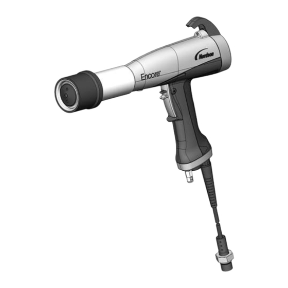
Description Section 2 Description Introduction See Figure 2-1. This manual covers the Encore Manual Porcelain Enamel Powder Spray Gun and Encore LT Manual Controller. Spray Gun Controller (Shown with Rail Mount Kit Installed) Figure 2-1 Encore Manual PE Powder Spray Gun and Encore LT Controller... -
Page 12: Specifications
Î Î Î Î Î Î Î Î Î Controller Certification Label ENCORE LT EN 50050 FM11ATEX0057X (2) 3 D Ex tc IIIC T60°C Dc T = +15 to +40°C NORDSON CORP. AMHERST, OH, USA Vn=100−250Vac 7n=50−60Hz Pn=100VA OUTPUT: V = +19V Io = +1.0A (peak) (peak) WARNING −... -
Page 13: System Setup
5. Rail bracket 8. M8 x 70 screws 2. M5 x 12 screws 6. Rail 9. #10 dished lock washer 3. M8 x 40 screws 7. M8 lock washers 10. Parts tray 4. M8 jam nuts Part 1602221-01 E 2012 Nordson Corporation... -
Page 14: System Connections
6mm black Encore LT Atomizing Air 8mm blue Controller Flow Air 8mm black Fluidizing Air 6mm blue Pump 10mm Filter Pickup Tube Feed Hopper Ground 10mm Input Air Figure 3-2 Powder System Block Diagram Part 1602221-01 E 2012 Nordson Corporation... -
Page 15: System Setup
Pull back on the knurled coupling rings to uncouple them. Figure 3-3 Pick-Up Tube and Pump Installation 1. Pickup tube 5. Encore PE pump 9. Throat holder 2. Lock nut 6. Conductive O-ring 10. -
Page 16: Spray Gun Connections
6. Connect the 6-mm black tubing to the purge air quick-disconnect fitting (8). Hose Adapter 4-mm Clear Electrode Gun Cable Air Wash Tubing 6-mm Black 1/2 in. Powder Hose Purge Air Tubing Figure 3-4 Gun Connections Part 1602221-01 E 2012 Nordson Corporation... -
Page 17: Bundling Tubing And Cable
50-lb hoppers supplying manual guns. (BROWN) (GRN/YEL) (BLUE) Figure 3-5 Encore LT Gun Controller Connections 1. Electrostatic ground (to cart or booth) 5. Air supply (blue, 10mm) 9. Fluidizing air (blue, 6mm) 2. Not used 6. Electrode air wash (clear, 4mm, 10. -
Page 18: System Air Supply
Air Filter Installation − Wall and Rail Mount Systems 1. 10-mm air tubing (blue) 4. Bracket 6. Release latch 2. 10-mm tube x 1/2 male connectors 5. Flow indicator 7. Customer-supplied fasteners 3. M5 screws Part 1602221-01 E 2012 Nordson Corporation... -
Page 19: Power Supply
KV/μA panel in the form N.NN for 1 second. NOTE: If the spray gun is triggered on during power-up or wake up from disable, the trigger LED blinks at a fast rate. Release the trigger and repeat the sleep/wake up cycle. Part 1602221-01 E 2012 Nordson Corporation... -
Page 20: Entering Configuration Mode
Electrostatic Control and Powder Flow Control modes. Function No. Name Settings Default Gun Type 0 = Encore Fluidizing 0 = Hopper, 1 = Box, 3 = Disable Electrostatic Control 0 = Custom, 1 = Classic Powder Flow Control 0 = Smart, 1 = Classic... -
Page 21: Operation
Trigger LED Enable/Disable Flow Air Select Charge (Classic) Mode Settings Powder Flow Rate (Smart Flow) KV/μA Panel Smart Flow Mode Indicator KV/μA Display Selection Atomizing Air (Classic) Total Flow (Smart Flow) Figure 4-1 Controller Interface Part 1602221-01 E 2012 Nordson Corporation... -
Page 22: Displays And Leds
Metallics Deep Recesses Re-Coat Figure 4-2 Select Charge Modes NOTE: If you press the STD/AFC selection button while using a Select Charge mode, the controller switches to Classic or Custom mode. Part 1602221-01 E 2012 Nordson Corporation... -
Page 23: Custom Electrostatic Mode
Press the + or − buttons to select the desired kV setpoint. The longer a button is pressed the faster the units change. The valid STD range is 0 or 25−100 kV. μA Figure 4-3 Display and STD/AFC Selection for Classic Mode Part 1602221-01 E 2012 Nordson Corporation... -
Page 24: Classic Afc Mode
Classic Flow mode, the Smart Flow LED is off. NOTE: Refer to page 3-8 for a list of the mode defaults and configuration instructions. Flow Air % or Flow Air Total Flow or Atomizing Air Figure 4-4 Flow Setting Panels Part 1602221-01 E 2012 Nordson Corporation... -
Page 25: Smart Flow Mode Settings
Setting values for both are 0−99% of maximum air pressure. Press the + and − buttons to enter the desired setpoint. The longer a button is pressed the faster the units change. Part 1602221-01 E 2012 Nordson Corporation... -
Page 26: Spray Gun Operation
Electrode air wash air continually washes the spray gun electrode to prevent powder from collecting on it. Electrode air wash air is turned on and off automatically when the spray gun is triggered on and off. Part 1602221-01 E 2012 Nordson Corporation... -
Page 27: Daily Operation
P on the flow display. Purge the gun periodically to keep the powder path inside the spray gun clean. The purge length and frequency needed depend on the application and powder. Part 1602221-01 E 2012 Nordson Corporation... -
Page 28: Cleaning Flat And Corner Spray Nozzles
6. Install the nozzle onto the electrode support (6), then screw the nozzle nut onto the gun body clockwise until finger-tight. 7. Press the Enable/Disable button to wake up the controller and resume operation. Part 1602221-01 E 2012 Nordson Corporation... -
Page 29: Cleaning Conical Nozzles And Deflectors
Refer to Electrode Support Repair in the Repair section. 5. Clean all parts with low-pressure compressed air. Inspect all parts and replace any that are worn or damaged. Part 1602221-01 E 2012 Nordson Corporation... -
Page 30: Changing From Conical To Flat Or Corner Spray Nozzle
Refer to Parts for optional nozzles, nozzle nut, and electrode holder kit. WARNING: Turn off the spray gun and ground the electrode before performing this procedure. Failure to observe this warning could result in a severe electrical shock. Part 1602221-01 E 2012 Nordson Corporation... -
Page 31: Shutdown
3. Turn off the system air supply and relieve the system air pressure. 4. If shutting down for the night or a longer period of time, disconnect power to the controller. 5. Perform the Daily Maintenance procedures on page 4-12. Part 1602221-01 E 2012 Nordson Corporation... -
Page 32: Maintenance
Check the system air filter. Drain the filter and change the filter element as needed. Refer to Parts for the replacement element part number. Check all system ground connections. Part 1602221-01 E 2012 Nordson Corporation... -
Page 33: Troubleshooting
These troubleshooting procedures cover only the most common problems. If you cannot solve a problem with the information given here, contact your contact Nordson technical support at (800) 433−9319 or your local Nordson representative for help. Controller Faults... -
Page 34: General Troubleshooting Chart
Replace worn parts. Plugged electrode support or Remove and clean the electrode powder path assembly. Remove and clean the spray gun powder path (inlet tube, outlet tube, electrode support) if necessary. Continued... Part 1602221-01 E 2012 Nordson Corporation... - Page 35 Orifice size is .25−.3 mm. Clean with an appropriate tool. Continued... Part 1602221-01 E 2012 Nordson Corporation...
- Page 36 11. No powder flow when Flow Air or Total Flow set to zero Change settings to a non-zero gun is triggered On, number. kV OK Input air turned OFF Make sure air is being supplied to the controller. Part 1602221-01 E 2012 Nordson Corporation...
-
Page 37: Spray Gun Power Supply Resistance Test
19−21 megohms. If the resistance is out of this range repair or replace the electrode support assembly . Refer to Electrode Support Repair in the Repair section to repair the electrode support assembly. 19−21 Megohms Figure 5-9 Electrode Support Resistance Test Part 1602221-01 E 2012 Nordson Corporation... -
Page 38: Gun Cable Continuity Test
(N/C) J1−1 J1−3 J3−2 J3−4 (ORANGE) (RED) (ORANGE) (WHITE) J3−3 (GREEN) J2−1 J2−3 J1−6 (RED) J1−4 (YELLOW) J2−2 (GREEN) (WHITE) (BLACK) J1−5 J2 (FACE VIEW) (YELLOW) POWER SUPPLY CONNECTOR Figure 5-10 Gun Cable Wiring Part 1602221-01 E 2012 Nordson Corporation... -
Page 39: Repair
Power Supply Trigger Connectors Connectors Figure 6-1 Gun Disassembly 28. Housing cover 30. Hook 31B. M3 x 20 screw 29. Display housing 31A. M3 x 30 screw Part 1602221-01 E 2012 Nordson Corporation... - Page 40 Figure 6-2 Removing the Gun Body from the Handle 20. Gun body 22. Powder outlet tube 44. Black nylon M5 screw 20A. Air wash tubing (filter assembly) 40. Handle Part 1602221-01 E 2012 Nordson Corporation...
-
Page 41: Power Supply Replacement
3. Pull the base away from the handle, swing the bottom of the ground pad (27) up and away from the handle, then remove it. Leave the ground wire connected to the ground pad. Part 1602221-01 E 2012 Nordson Corporation... -
Page 42: Powder Path Installation
(27) into the body and rotate it onto the handle. Make sure the cable wires are not pinched or trapped during re-assembly. 4. Install the handle base onto the handle and ground pad and secure it with the two M3 x 20 screws (31B). Part 1602221-01 E 2012 Nordson Corporation... -
Page 43: Gun Reassembly
While pushing the body and handle together, use your finger to make sure the end of the outlet tube fits into the hole in the front of the gun body. Part 1602221-01 E 2012 Nordson Corporation... -
Page 44: Cable Replacement
9. Carefully disconnect the round trigger connector from the trigger switch connector. 10. Pull the cable out of the handle base, feeding the connectors through the base one at a time. Part 1602221-01 E 2012 Nordson Corporation... -
Page 45: Cable Installation
6. Push the handle base (39) up against the handle and ground pad, and tighten securely the two M3 x 20 screws (31B) in the base. 7. See Figure 6-1. Install the bottom M3 x 20 screw (31B) in the housing (29) and tighten it securely. Part 1602221-01 E 2012 Nordson Corporation... -
Page 46: Trigger Switch Replacement
5. See Figure 6-8. Insert a small flat-bladed screwdriver behind the clear pull tab at the top of the switch, then grasp the pull tab with a finger and gently pull it away from the handle. Figure 6-8 Removing the Trigger Switch from the Handle Part 1602221-01 E 2012 Nordson Corporation... -
Page 47: Switch Installation
6. Make sure the ribbon cable is not trapped or pinched, then press the switch against the back of the recess. Run your finger up and down on the switch to ensure it is securely adhered to the handle. Part 1602221-01 E 2012 Nordson Corporation... - Page 48 9. Connect the trigger switch connector to the round cable connector, then tuck the connectors back up to the handle. 10. Re-install the ground cover as described in Cable Installation steps 5−7 on page 6-7. Part 1602221-01 E 2012 Nordson Corporation...
-
Page 49: Controller Repair
Refer to Section 5, Troubleshooting, for the controller electrical schematic and harness connections. Refer to Section 7, Parts for repair kits. Figure 6-12 Controller Front Panel 1. Bezel 2. Keypad 3. Main control board Part 1602221-01 E 2012 Nordson Corporation... -
Page 50: Rear Panel Components
1. Manifold assembly 4. Line filter 7. Air wash air solenoid valve 2. Relay board 5. Fluidizing air solenoid valve 8. Flow-rate air regulator 3. Power supply 6. Purge air solenoid valve 9. Atomizing air regulator Part 1602221-01 E 2012 Nordson Corporation... -
Page 51: Parts
Support Center at (800) 433-9319 or contact your local Nordson representative. This section covers parts for the Encore LT spray gun, controller, system components and parts, powder and air tubing, and options. Refer to the following manuals for additional information and optional equipment. - Page 52 Parts Figure 7-1 Exploded View of Encore PE Manual Spray Gun and Accessories Part 1602221-01 E 2012 Nordson Corporation...
- Page 53 Description Quantity Note − 1601416 SPRAY GUN, manual, Encore PE 1601811 S RETAINER, deflector, 38 mm, Encore PE 245523 S DEFLECTOR, 38 mm diameter, ceramic 945016 S S O-RING, silicone, 0.251 x 0.40 x 0.074 in. 246578 S INSERT, Pyrex 940331 S O-RING, silicone, 2.00 x 2.175 x 0.063 in.
- Page 54 Parts Item Part Description Quantity Note 1601439 S INLET assembly, powder, Encore PE 1084773 S S O-RING, silicone, 18 mm ID x 2 mm W, 70 duro 1601756 S ADAPTER assembly, hose, spray gun, M, Encore PE 940157 S S O-RING, Viton, black, 0.563 x 0.688, 10415...
-
Page 55: Spray Gun Options
Part Description Quantity Note 1085168 CABLE, 6 meter extension, shielded, Encore manual NS: Not Shown Optional Flat and Corner Spray Nozzles Spray guns are shipped with a conical nozzle. If replacing the conical nozzle with an optional flat or corner spray nozzle, order a new nozzle nut and flat spray electrode holder kit along with a nozzle. -
Page 56: Controller Parts
Parts Controller Parts Front Panel and Internal Cabinet Ground Rear Panel Assembly See Figures 7-4 and 7-5 for parts Figure 7-3 Controller Parts Part 1602221-01 E 2012 Nordson Corporation... -
Page 57: Front Panel And Internal Cabinet Ground Parts List
Quantity Note − 1107552 CONTROLLER ASSY, manual, Encore LT, packaged 1108279 S KIT, PCA, control, Encore LT 1108312 S PANEL, keypad, Encore LT/auto controller, packaged 982916 S SCREW, flat, socket, M5 x 10, black 982636 S SCREW, button, socket, M5 x 12, zinc... -
Page 58: Rear Panel Parts
Parts Rear Panel Parts Manifold Assembly See Figure 7-5 (this screw only) Figure 7-4 Rear Panel Parts Part 1602221-01 E 2012 Nordson Corporation... -
Page 59: Rear Panel Parts List
972808 S CONNECTOR, strain relief, 1/2 in. NPT 984192 S NUT, lock, 1/2 in. NPT, nylon 117549 S GASKET, panel, rear, Encore LT controller 982824 S SCREW, pan head, recessed, M3 x 8, with lockwasher, black 1107696 S FILTER, line, RFI power, 3A, with 0.250 QD... -
Page 60: Manifold Parts
1/8 unithread 1107595 S VALVE, flow control, 6 mm x 1/8 unithread 1108313 S MUFFLER, exhaust, R1/8 1107593 S GASKET, manifold, controller, Encore LT 1107597 S REGULATOR, electro-pneumatic 1099281 S VALVE, solenoid, 3 port, 24V, 0.35W Part 1602221-01... -
Page 61: System Components And Parts
NOTE A: Minimum order quantity is 50 ft. System Options Part Description Quantity Note 1091429 KIT, input air, Encore manual systems 972841 S CONNECTOR, male, 10 mm tube x in. unithread 971102 S CONNECTOR, male, 10 mm tube x in. unithread... - Page 62 7-12 Parts Part 1602221-01 E 2012 Nordson Corporation...
-
Page 63: Wiring Diagram
Wiring Diagram Section 8 Wiring Diagram Part 1602221-01 E 2012 Nordson Corporation... - Page 64 Wiring Diagram Part 1602221-01 E 2012 Nordson Corporation...
- Page 65 230V MOTOR M1 M2 M3 M1 M2 M3 A.C. POWER HARNESS NO.1 (GROUND JUMPER 2) 15 FT (4.6M) POWER CORD CONTROLLER CABINET NO.4 VBF POWER CORD WIRING Figure 8-1 Encore LT Manual Controller Wiring Diagram Part 1602221-01 E 2012 Nordson Corporation...
-
Page 66: Declaration Of Conformity
DECLARATION of CONFORMITY PRODUCT: Models: Encore PE Manual Applicators for use with Encore or Encore LT Manual Controllers. Description: This is a manual electrostatic powder spray system, including applicators, control cables and associated controllers used for spraying porcelain enamel powders. The porcelain enamel powders are non-flammable.
Need help?
Do you have a question about the Encore and is the answer not in the manual?
Questions and answers