Nordson Encore HD Manual
Pump control unit and power supply
Hide thumbs
Also See for Encore HD:
- Customer product manual (273 pages) ,
- Product manual (68 pages) ,
- Operator card (11 pages)
Table of Contents
Advertisement
Quick Links
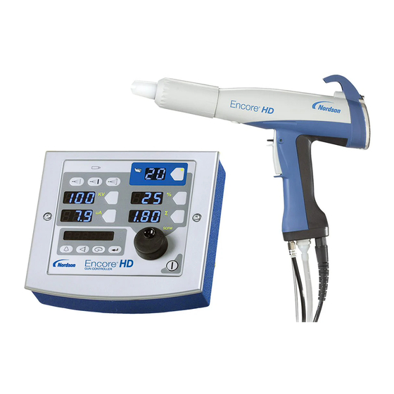
Encore® HD/XD Pump
Control Unit and
Power Supply
Customer Product Manual
Document Number
1606783-10
Issued 04/24
For parts and technical support, call the Industrial Coating
Systems Customer Support Center at (800) 433-9319 or
contact your local Nordson representative.
This document is subject to change without notice.
Check
http://emanuals.nordson.com
for the latest version.
NORDSON CORPORATION • AMHERST, OHIO • USA
Advertisement
Chapters
Table of Contents
Troubleshooting

Related Manuals for Nordson Encore HD


Summary of Contents for Nordson Encore HD
- Page 1 For parts and technical support, call the Industrial Coating Systems Customer Support Center at (800) 433-9319 or contact your local Nordson representative. This document is subject to change without notice. Check http://emanuals.nordson.com for the latest version. NORDSON CORPORATION • AMHERST, OHIO • USA...
- Page 2 Nordson Corporation welcomes requests for information, comments, and inqui- This is a Nordson Corporation publication which is protected by copyright. ries about its products. General information about Nordson can be found on the Original copyright date 2015. No part of this document may be photocopied,...
-
Page 3: Table Of Contents
Regulator Adjustment ........................iFlow Module Repair ........................Testing iFlow Modules ........................Conveyance Air Flow ........................Pattern Air ............................ Solenoid Valve Replacement ......................Proportional Valve Cleaning ......................Proportional Valve Replacement ....................Vibrator Motor Replacement ......................Pump ............................. 1606783-10 ©2024 Nordson Corporation... - Page 4 Using the Illustrated Parts List ...................... Pump Control Unit ......................... Panel Assembly ..........................Panel Assembly (contd) ........................ iFlow Module ..........................Manifold Assembly ........................Wall/Rail Mount System ....................... 7-10 Powder Hose and Air Tubing ....................... 7-10 Miscellaneous Options ........................7-11 Wiring Diagrams ........................... 1606783-10 ©2024 Nordson Corporation...
-
Page 5: Change Record
10/15 New release 03/16 Updated gaskets. 1/18 Updated for new Encore HD pump information. 11/18 Replacing part number 1606690 with 1615026 Update part lists for pump control, panel assembly, manifold assembly, pump, spare 6/19 parts, powder hose and air tubing. - Page 6 Change Record 1606783-10 ©2024 Nordson Corporation...
-
Page 7: Safety
Intended Use Use of Nordson equipment in ways other than those described in the documentation supplied with the equipment may result in injury to persons or damage to property. Some examples of unintended use of equipment include: •... -
Page 8: Personal Safety
• Clean, maintain, test, and repair equipment according to the instructions in your equipment documentation. • Use only replacement parts that are designed for use with original equipment. Contact your Nordson representative for parts information and advice. 1606783-10 © 2024 Nordson Corporation... -
Page 9: Grounding
• Disconnect and lock out system electrical power. Close hydraulic and pneumatic shutoff valves and relieve pressures. • Identify the reason for the malfunction and correct it before restarting the system. Disposal Dispose of equipment and materials used in operation and servicing according to local codes. 1606783-10 © 2024 Nordson Corporation... - Page 10 1-4 Safety 1606783-10 © 2024 Nordson Corporation...
-
Page 11: Overview
See Figure 2-1. This manual covers the Encore® HD/XD pump control unit, which is used to supply power and to operate Encore HD manual powder spray systems. The pump control unit comes equipped with a Encore HD/XD powder feed pump. The unit contains the pneumatic circuit, which controls all pump, color change, and vibratory box feed (VBF) functions. -
Page 12: Specifications
2-2 Overview Specifications Model: Encore HD/XD Controller Power Unit Input Rating: 100−240 VAC, 50/60 Hz, 125 VA Output Rating: 24 VDC, 2.5 A 6.0−6.9 bar (87−100 psi), Input Air: <5µ particulates, dew point <10 °C (50 °F) Max Relative Humidity: 95% non-Condensing +15 to +40 °C... - Page 13 375 mm 318 mm 304 mm (14.8 in.) (12.9 in.) (11.9 in.) 217 mm (8.6 in.) Figure 2-2 Encore HD Controller Power Unit Dimensions 179 mm 296 mm (7.0 in.) (11.6 in.) 370 mm 375 mm (14.5 in.) (14.8 in.) 304 mm (11.9 in.)
-
Page 14: Pump Control Unit Certification Label
High Pinch Valve Regulates the high pinch valve pressure 80 psi Low Pinch Valve Regulates the low pinch valve pressure 37 psi Regulates the supply from the vacuum Vacuum Generator Regulator 80 psi generator 1606783-10 © 2024 Nordson Corporation... - Page 15 Overview Figure 2-4 Pump Control Manifold 1606783-10 © 2024 Nordson Corporation...
- Page 16 2-6 Overview This page intentionally left blank. 1606783-10 © 2024 Nordson Corporation...
-
Page 17: Installation
See Figure 3-1 and Figure 3-2. Using the supplied brackets, the power unit can be mounted to a wall or rail, as desired. Wall Mount Configuration Rail Mount Configuration Figure 3-1 Controller with Mounting Brackets 1606783-10 © 2024 Nordson Corporation... -
Page 18: Pump Control Unit Mount (Contd)
Fasteners shown are provided with the controller. Make sure to provide clearance for the connections to both the power unit and the interface module. Figure 3-2 Pump Control Unit Wall Mounting Brackets 1. Pump control unit 2. Wall mount bracket 3. Rail mount bracket 1606783-10 © 2024 Nordson Corporation... -
Page 19: Interconnect Cable Connection
Interconnect Cable Connection See Figure 3-3. Connect the gray, 3 meter (10 ft) interconnect cable to the net/auxiliary receptacles on Encore HD/XD system controller to the pump control unit. NOTE: The interconnect cable shipped with the system is 3 meters (10 ft) long. If a longer length is desired, you must order additional cables. -
Page 20: System Connections
For additional information, see the Wiring Diagrams section. Encore HD Manual Powder Spray Gun Hopper Pump Vacuum Pinch Pump Hi/Lo Manifold Purge Encore HD Flow Module Figure 3-4 Encore HD/XD Pump Control Unit Pneumatic Diagram 1606783-10 © 2024 Nordson Corporation... - Page 21 Spray Gun System Controller Pump Manifold Pump Purge Valve Pinch Hi/Low Valve Blue LED Encore HD Flow Module AC Power Relay/ Power Supply Filter Fuses VBF Motor Figure 3-5 Encore HD/XD Pump Control Unit Electrical Diagram 1606783-10 © 2024 Nordson Corporation...
-
Page 22: Pump Control Unit Connections
3-6 Installation Pump Control Unit Connections The Encore HD spray gun is controlled by the system controller and pump control unit connected by a network/power cable. The pump control unit houses a 24Vdc power supply, circuit board, and iFlow® air controller and valves used to control the Encore HD/XD pump. -
Page 23: Spray Gun Connections
3. Thread the cable nut onto the receptacle and tighten the nut securely. Net Cable Cable to (To Pump Control Unit) Spray Gun Figure 3-7 Spray Gun Cable Connection to System Controller − Mobile System Shown 1606783-10 © 2024 Nordson Corporation... -
Page 24: Air Tubing And Powder Tube
HD Tube Adapter 4-mm Clear Electrode Air Wash Tubing Spray Gun Cable 8 mm Powder Hose 6-mm Blue Pattern Air Tubing Figure 3-8 Spray Gun Connections 1606783-10 © 2024 Nordson Corporation... -
Page 25: Bundling Tubing And Cable
Close the tube holders, being careful not to over tighten. Spiral wrap is used to protect the tubing from the swivel castors. For Standalone and Rail/Wall systems: The tubing must be coiled in a 3 ft diameter in a horizontal orientation. 1606783-10 © 2024 Nordson Corporation... -
Page 26: Main System Air And Electrical Connections
The air must be clean and dry. A refrigerant or desiccant-type air drier and air filters are recommended. 10-mm Air Tubing Output to Pump Control Unit 12-mm Air Tubing Supply Air Input Air Filter Figure 3-10 System Air Supply Connection (Shown with Mobile System) 1606783-10 © 2024 Nordson Corporation... -
Page 27: Standalone, Rail Mount, And Wall Mount System Air Supply
10-mm Air Tubing Out to Pump Control Unit Figure 3-11 Air Filter Installation − Standalone and Rail/Wall Mount Systems 1. Flow indicator 3. 10-mm dual connector 5. 12-mm elbow connector 2. 10-mm elbow connector 4. Bracket 1606783-10 © 2024 Nordson Corporation... -
Page 28: Powder Pump Hose
3. Push the flexible powder tubing (4) over the barbed ending of the adapter (2). Semi-Rigid Tubing Flexible Tubing Figure 3-12 Pump Tubing Installation 1. Lower Y block 3. Semi-rigid tubing 2. Barbed tubing adapter 4. Flexible tubing 1606783-10 © 2024 Nordson Corporation... -
Page 29: Pump Adapter Installation
See Figure 3-13. The pump adapter allows you to connect the pump to your powder source. Install the tubing onto the barbed hose adapter. Then, plug the barbed hose adapter into the pump adapter. Pump Adapter Figure 3-13 Pump Mounting with Adapter on HR or NHR Hoppers 1606783-10 © 2024 Nordson Corporation... -
Page 30: Electrical Connections
Use the ESD ground bus bar kit included with the system to connect the power unit ground stud to the grounded spray booth or a true earth ground. Refer to the instructions included with the kit. 1606783-10 © 2024 Nordson Corporation... -
Page 31: Operation
For pump information, refer to the pump manual. European Union, EX, Special Conditions for Safe Use 1. The Encore XT/HD Interface Control Unit and the Encore HD Controller Power Unit or a Mobile Powder Systems shall only be used over the ambient temperature range of +15°C to +40°C with the Encore HD Powder Electrostatic Manual Applicator or with... - Page 32 4-2 Operation 1606783-10 © 2024 Nordson Corporation...
-
Page 33: Troubleshooting
Failure to observe this warning could result in personal injury. These troubleshooting procedures cover only the most common problems. If you cannot solve a problem with the information given here, contact Nordson technical support at (800) 433−9319 or your local Nordson representative for help. NOTE: For pump information, refer to the pump manual. -
Page 34: Manifold Troubleshooting
Repair in Repair section for instructions. 4. Spray gun fan Defective pattern air flow pattern changes control valve If the problem persists, replace the pattern air flow control valve. Refer to iFlow Module Repair in Repair section for instructions. 1606783-10 © 2024 Nordson Corporation... -
Page 35: Solenoid And Flow Control Valve Functions
Left Side Suction Pinch Valve Right Side Delivery Pinch Valve Vacuum Generator Right Side Fluidizing Tube High Pinch Valve (80 psi) Left Side Fluidizing Tube Low Pinch Valve (37 psi) Left Side Delivery Tube Vacuum Generator Regulator (80 psi) 1606783-10 © 2024 Nordson Corporation... -
Page 36: Re-Zero Procedure
1. At the pump control panel, disconnect the 6 mm pattern air tubing and install 8-mm plugs in the output fittings. 2. Press the Nordson button for 5 seconds to display the controller functions. F00−00 is displayed. 3. Rotate the knob until F10−00 is displayed. -
Page 37: Repair
Electrostatic sensitive device. To avoid damaging the controller circuit boards, wear a grounding wrist strap and use proper grounding techniques when making repairs. Refer to the Wiring Diagram section for the pump control unit electrical schematic and harness connections. 1606783-10 © 2024 Nordson Corporation... -
Page 38: Removing Panel Assembly
Handle cable and connectors with care. When reassembling, do not allow cables or air lines to become pinched or twisted at the back of the cabinet wall. External Enclosure Ground Internal Enclosure Ground Figure 6-1 Sub-Panel Removal 1. Enclosure 2. Screws 3. Panel assembly 1606783-10 © 2024 Nordson Corporation... -
Page 39: Sub-Panel Components
1. Unplug one of the fittings from the regulator and plug the gauge into the fitting. 2. Set the regulator to 85 psi. 3. Remove the gauge and replace the plug in the regulator fitting. 4. Push the regulator knob to lock the setting. Fittings Figure 6-2 Regulator Adjustment 1606783-10 © 2024 Nordson Corporation... - Page 40 6-4 Repair This page intentionally left blank. 1606783-10 © 2024 Nordson Corporation...
-
Page 41: Iflow Module Repair
4. Decrease the assist air to −50% and trigger the pump ON. The monometer should read 1.0−3.0 psi (0.1−0.2 bar). Pattern Air Use the flow verification tool (1039881) with its instructions and connect to the pattern air output. 1606783-10 © 2024 Nordson Corporation... -
Page 42: Solenoid Valve Replacement
See Figure 6-3. If cleaning the proportional valve does not correct the flow problem then replace the valve. Before installing a new valve, remove the protective cover from the bottom of the valve body. Be careful to not lose the O-rings under the cover. 1606783-10 © 2024 Nordson Corporation... - Page 43 2. Nut−coil to proportional valve (2) 7. Direction of flow arrow 11. Valve body 3. Coil−proportional valve (2) 8. Stem 12. Orifice 4. Long screws−valve to manifold (2) 9. Spring 13. Solenoid valves 5. Short screws−valve stem to body (2) 1606783-10 © 2024 Nordson Corporation...
-
Page 44: Vibrator Motor Replacement
Check the ID plate on the power unit. Replacement motors include the power cable. Refer to the Power Unit Wiring Diagram in the Troubleshooting section of this manual for internal VBF wiring. Pump NOTE: For pump information, refer to the pump manual. 1606783-10 © 2024 Nordson Corporation... -
Page 45: Parts
A dash (—) is used when the part number applies to all parts in the illustration. The number in the Part column is the Nordson Corporation part number. A series of dashes in this column (- - - - - -) means the part cannot be ordered separately. -
Page 46: Pump Control Unit
• VALVE, flow control, 4 mm x 1/8 uni 984526 • NUT, lock, 1/2 conduit 939122 • SEAL, conduit fitting, ½, blue 1605823 • HARNESS, receptacle out, VBF, controller, Encore HD 1023695 • SEAL, bulkhead, 7/8−16 thread 972930 • PLUG, push-in, 8 mm T, plastic 1603928 •... - Page 47 Parts 17,18,19,20 Figure 7-1 Pump Control Unit 1606783-10 © 2024 Nordson Corporation...
-
Page 48: Panel Assembly (Contd)
• PUMP ASSEMBLY 1027585 • VALVE, solenoid, 3−way, sub base 1605442 • MODULE, digital air flow, manual system, Encore HD 1604082 • VALVE, solenoid, 3−port, 24 vdc, ¼ NPTF 1100310 • REGULATOR, 1/8 , 1/4 NPT, 7−125 psi, pneumatic panel 1052893 •... - Page 49 Parts Figure 7-2 Panel Assembly Parts (1 of 2) 1606783-10 © 2024 Nordson Corporation...
- Page 50 • POWER SUPPLY, 24 Vdc, 60 W 1604518 • CONNECTOR, male, elbow, 6 mm T x 1/8 RPT 1604804 • MANIFOLD ASSEMBLY, pump control, Encore HD 1605754 • FILTER, line, with terminals, Encore HD 984702 • NUT, hex, M5, brass 983021 •...
-
Page 51: Iflow Module
• VALVE, solenoid, 3-way, w/connector 1027547 • VALVE, proportional, solenoid, sub-base - - - - - - • PCA, Encore HD flow node, 1 channel 972277 • CONNECTOR, male, elbow, 8 mm T x 1/4 uni 972399 • CONNECTOR, male, with/int hex, 6 mm T x 1/8 uni 1030873 •... -
Page 52: Manifold Assembly
Note — 1620531 MANIFOLD ASSEMBLY, pump control, Encore HD 1620533 • GASKET, pump control manifold, Encore HD 972094 • CONNECTOR, male, 90 elbow, 12 mm T x 3/8 UNI 1099281 • VALVE, solenoid, 3 port, 24 V, 0.35 W - - - - - - •... - Page 53 Parts Figure 7-5 Manifold Assembly Parts 1606783-10 © 2024 Nordson Corporation...
-
Page 54: Wall/Rail Mount System
Do not replace with non-conductive tubing. F. Standard powder hose delivered with system. G. Optional powder hose to use in place of the standard polyolefin. 1606783-10 © 2024 Nordson Corporation... -
Page 55: Miscellaneous Options
Miscellaneous Options Part Description Quantity Note 1091429 KIT, input air, Encore HD manual systems 972841 • CONNECTOR, male, 10 mm tube x 1/4 in. unithread 971102 • CONNECTOR, male, 10 mm tube x 3/8 in. unithread 973500 • COUPLING, pipe, hydraulic, 1/4 in., steel, zinc 973520 •... - Page 56 7-12 Parts 1606783-10 © 2024 Nordson Corporation...
-
Page 57: Wiring Diagrams
Wiring Diagrams Section 8 Wiring Diagrams Description Part Number Encore HD Power/Pneumatic Controller Assembly 10013427 1606783-10 © 2024 Nordson Corporation... - Page 58 8-2 Wiring Diagrams 1606783-10 © 2024 Nordson Corporation...
- Page 59 MATERIAL NO. REVISION 10013427 NOTICE THIS DRAWING IS NORDSON PROPERTY,CONTAINS PROPRIETARY INFORMATION AND MUST BE RETURNED UPON REQUEST. DO NOT CIRCULATE, REPRODUCE OR DIVULGE TO OTHER PARTIES WITHOUT WRITTEN CONSENT OF NORDSON. CHECK VALVE ATOMIZING AIR CONNECT TO ELECTRODE AIR WASH...
- Page 60 MATERIAL NO. REVISION 10013427 NOTICE THIS DRAWING IS NORDSON PROPERTY,CONTAINS PROPRIETARY INFORMATION AND MUST BE RETURNED UPON REQUEST. DO NOT CIRCULATE, REPRODUCE OR DIVULGE TO OTHER PARTIES WITHOUT WRITTEN CONSENT OF NORDSON. CONNECTOR FOR LED ENCORE DIGITAL AIRFLOW CONTROL MODULE...
-
Page 61: Eu Declaration Of Conformity
Description: These are electrostatic, powder spray systems, including applicator, control cables and associated controllers. The Encore XT Manual system uses venturi style pump technology for supplying powder to the spray gun. While the Encore HD Manual system uses high density pump technology for supplying powder to the spray gun. - Page 62 Description: These are electrostatic, powder spray systems, including applicator, control cables and associated controllers. The Encore XT Manual system uses venturi style pump technology for supplying powder to the spray gun. While the Encore HD Manual system uses high density pump technology for supplying powder to the spray gun.
- Page 63 For parts and technical support, call the Industrial Coating Systems Customer Support Center at (800) 433-9319 or contact your local Nordson representative. This document is subject to change without notice. Check http://emanuals.nordson.com for the latest version. NORDSON CORPORATION • 100 NORDSON DRIVE AMHERST, OHIO 44001• USA...
- Page 64 Nordson Corporation welcomes requests for information, comments, and This is a Nordson Corporation publication which is protected by copyright. inquiries about its products. General information about Nordson can be found on Original copyright date 2017. No part of this document may be photocopied,...
- Page 65 10/23 Removed P/N 1620004 & P/N 768181, Added P/N 7035356 per tubing consolidation 04/24 Updating parts and service kits. Removed HD+ references. Updated lower Y-block. 08/24 Updated parts section for clarification on kits and available parts. 1605708-11 ©2024 Nordson Corporation...
- Page 66 Change Record 1605708-11 ©2024 Nordson Corporation...
-
Page 67: Safety
• Obtain and read Material Safety Data Sheets (SDS) Use of Nordson equipment in ways other than those for all materials used. Follow the manufacturer’s described in the documentation supplied with the instructions for safe handling and use of materials, and equipment may result in injury to persons or damage to use recommended personal protection devices. -
Page 68: Fire Safety
• Use only replacement parts that are designed for use with original equipment. Contact your Nordson Action in the Event of a Malfunction representative for parts information and advice. If a system or any equipment in a system malfunctions,... -
Page 69: Description
Encore® HD/XD Pump Description Pump See Figure 1. The Encore HD and XD powder feed pump transports precise amounts of powder from a feed source to a powder spray gun. Encore HD Encore XD Figure 1 Encore HD/XD Pump Features and Benefits •... -
Page 70: Pump Components
Inlet Fitting Connects to the tubing leading from the power source Outlet Fitting Connects to the tubing leading to the powder spray gun Encore HD Pump Encore XD Pump Figure 2 Encore HD/XD Pump Components 1605708-11 © 2024 Nordson Corporation... -
Page 71: Theory Of Operation
Encore® HD/XD Pump Theory of Operation Pumping The Encore HD/XD pump consists of two halves that function identically. The halves alternately draw powder in and dispense powder out of the pump; while one half is Left half drawing powder in, the other half is dispensing powder out. -
Page 72: Purging
After the delivery side is purged, the delivery pinch valves close and the suction pinch valves open. The suction side is purged in the same way as the delivery side. Powder Figure 5 Purging Operation 1605708-11 © 2024 Nordson Corporation... -
Page 73: Pump Port Functions
Position Function Right Side Suction Pinch Valve Right Side Delivery Pinch Valve Right Side Fluidizing Tube Left Side Fluidizing Tube Left Side Delivery Pinch Valve Left Side Suction Pinch Valve Figure 6 Pump Port Functions 1605708-11 © 2024 Nordson Corporation... -
Page 74: Operation
Refer to the Operation section of the applicable and notify you that it is time to replace the fluidizing tubes. controller manual for specific instructions. Correct vacuum reading is (9-14 in. Hg). 1605708-11 © 2024 Nordson Corporation... -
Page 75: Specifications
7.40 in (25 mm) 9.13 in (188 mm) 9.34 in (232 mm) (237 mm) 11.10 in (282 mm) 2.89 in (74 mm) 2.89 in (74 mm) Encore HD Encore XD Figure 7 Encore Pump Dimensions 1605708-11 © 2024 Nordson Corporation... -
Page 76: Installation
Tubing Flexible Tubing Figure 8 Powder Tubing Installation Antistatic 8.2 mm OD/5.6 mm ID Tubing Refer to the Encore HD Antistatic Tubing Grounding Kit instruction sheet (1620023). Only used with Encore HD Antistatic Tubing Grounding Kit. 1605708-11 © 2024 Nordson Corporation... -
Page 77: Pump To Cabinet, Panel, Or Housing
3. Secure the pump hand tight to the cabinet wall with the replace both upper Y block and custom O-ring. pump mounting hardware (2). 4. Tighten all hardware securely. Figure 10 Pump Mounting to Cabinet Figure 11 Pump Ground Check 1605708-11 © 2024 Nordson Corporation... -
Page 78: Maintenance
Each Time the Pump Is NOTE: Torque screw to 25-30 in.-lb (2.8- Disassembled Lower Y Block 3.4 N●m) for assembly. Gasket Inspect the gasket for damage. Replace if necessary. 1605708-11 © 2024 Nordson Corporation... -
Page 79: Troubleshooting
These troubleshooting procedures cover only the most common problems that you may encounter. If you cannot solve the problem with the information given here, call the Nordson Finishing Customer Support Center at (800) 433-9319 or contact your local Nordson representative for help. - Page 80 The delivery tubing must be 60 ft from the pump to the spray gun. not to specification. Problem with pump or Perform Vacuum Check procedure in Troubleshooting section. pump control manifold. (Requires 0-30 in. Hg vacuum gauge.) Continued... 1605708-11 © 2024 Nordson Corporation...
- Page 81 2. Remove the vacuum generator vent hose at the bottom of the cabinet (inside). Trigger the spray gun on. Check for exhaust and increase the powder flow. 3. Check for proper direction of the check valve. 1605708-11 © 2024 Nordson Corporation...
-
Page 82: Vacuum Check
Suction Check finger over the fitting as shown in Figure 12. procedure. 4. Trigger the spray gun and watch the vacuum gauge or feel for the vacuum. Figure 12 Vacuum Check Options 1605708-11 © 2024 Nordson Corporation... - Page 83 9-14 in. HG Vacuum < 8 in. HG Gauge Reading Cycles Vacuum Side 1 Side 2 Side 1 Side 2 9-14 in. HG < 8 in. HG Vacuum Gauge Reading Cycles Figure 13 Vacuum Readings 1605708-11 © 2024 Nordson Corporation...
-
Page 84: Delivery Check
See Pump is bad, requires repair in the Troubleshooting 2. Trigger the gun and observe the powder flow. table. • If the problem remains, the pump control manifold is bad. See Pump is bad, requires repair in the Troubleshooting. Figure 14 Tubing Connections 1605708-11 © 2024 Nordson Corporation... -
Page 85: Repair
2. See Figure 16. Loosen the fluidizing tube access plug and pull the fluidizing tube straight out of the pump Retrofit Pump body. Retrofit Pump Standard Pump Standard Pump Figure 18 Reinstalling the Purge Air Tubing Figure 16 Loosening the Fluidizing Tubes 1605708-11 © 2024 Nordson Corporation... -
Page 86: Pump Disassembly
Refer to Replacing Pump Gasket in the Figure 19 Retrofit Pump Disassemble Preparation Repair section if replacement is needed. Figure 20 Standard Pump Disassemble Preparation 1605708-11 © 2024 Nordson Corporation... - Page 87 Encore® HD/XD Pump Figure 21 Pump Disassembly (Encore HD Shown) 1. Fitting caps (2) 9. Purge manifold (1) 16. Filter discs (4) 2. O-Rings (2) 10. Manifold gasket (1) 17. Pinch valve chamber block (1) 3. Check valves (2) 11. Block seal (1) 18.
-
Page 88: Pump Assembly
(16). Then, once that is complete, assemble the complete access plugs (15) and additional O-rings onto the fluidizing tubes (16). Figure 23 Assemble the Pinch Valve Housing Figure 25 Assemble Fittings to Fluidizing Tubes 1605708-11 © 2024 Nordson Corporation... -
Page 89: Replacing Pump Gasket
CAUTION: Ensure gasket is not covering any of the port holes on pump. A second gasket is Figure 28 Replacing Pump Gasket provided with pumps as an additional spare. 1605708-11 © 2024 Nordson Corporation... -
Page 90: Parts
To order parts, call the Nordson Industrial Coating Systems Customer Support Center at (800) 433-9319 or contact your local Nordson representative. See Figure 29 and the following parts lists. Figure 29 Encore HD and XD Standard Parts (shown with manual system pumps) 1605708-11 © 2024 Nordson Corporation... -
Page 91: Pump For Manual Systems
Pump for Automatic Systems Part Description Quantity Note 1612248 PUMP, Encore HD retrofit assembly 1612250 PUMP, Encore XD retrofit assembly Kits for Both Manual and Automatic System Pumps See Figure 29 and the following parts list. Pump Service Kits Item... -
Page 92: Kits For Both Manual And Automatic System Pumps Continued
SCREW, socket M5, shoulder, stainless steel, HD pump 1620035 SCREW, socket, M5, shoulder, blue, stainless steel, XD pump NOTE: A. If removing screw, replace lower conductive gasket (18). UA: Unavailable for purchase through Nordson. Contact local distributor or local source. 1605708-11 © 2024 Nordson Corporation... -
Page 93: Kits For Manual System Pumps
• O-RING, -013, 0.437 x 0.562 x 0.063 in., silicone, 70 Duro Check Valve Kit Item Description Quantity Note 1625733 - KIT, check valve, HD/XD pump — • VALVE ASSEMBLY, check, Encore HD • O-RING, -012, 0.375 x 0.500 x 0.063 in., silicone, 70 Duro 1605708-11 © 2024 Nordson Corporation... -
Page 94: Kits For Automatic System Pumps
Figure 30 Retrofit Fluid Tube and Plug Kit Item Description Quantity Note 1610812 - PLUG, retrofit, fluid tube, Encore HD — • CONNECTOR, 10 mm T x 3/8 uni • CHECK VALVE ASSEMBLY, pump • PLUG, retro, fluid tube access, Encore HD •... -
Page 95: Manifold Kit
1616440 - KIT, Encore to Prodigy manifold — • ADAPTER, Encore, HD pump to Prodigy manifold • GASKET, adapter, Encore HD pump to Prodigy 1625737 - KIT, adapter gasket, 8 pack, HD/XD pump — • GASKET, adapter, Encore HD pump to Prodigy... -
Page 96: Kits For Automatic System Pumps Continued
See Figure 32 and the following parts list. Item Description Quantity Note 1621252 - KIT, ground, pump controller, Encore HD — • JUMPER, ground, 72 in. • LUG, ground, dual tap • SCREW, socket set, 1/4-20 x 0.50, flat zinc •... -
Page 97: Air And Powder Tubing Part Numbers
NOTE: A. Barbed fitting required. B. Optional powder hose to use in place of the standard polyolefin. C. Encore HD antistatic tubing for eliminating turbo-charging. Must be used with Encore pump grounding kits 1620013 and 1621252. D. For purge air. - Page 98 32 Encore® HD/XD Pump 1605708-11 © 2024 Nordson Corporation...
Need help?
Do you have a question about the Encore HD and is the answer not in the manual?
Questions and answers