Table of Contents
Advertisement
Quick Links
Encore
VT Manual
®
Powder Spray System
Customer Product Manual
Document Number
1626653-01
- English -
Issued 01/25
For parts and technical support, call the Industrial Coating
Solutions Customer Support Center at (800) 433-9319 or
contact your local Nordson representative.
This document is subject to change without notice.
Check
http://emanuals.nordson.com
for the latest version.
NORDSON CORPORATION • 100 NORDSON DRIVE, AMHERST, OHIO 44001• USA
Advertisement
Table of Contents
Troubleshooting

Related Manuals for Nordson Encore VT


Summary of Contents for Nordson Encore VT
- Page 1 For parts and technical support, call the Industrial Coating Solutions Customer Support Center at (800) 433-9319 or contact your local Nordson representative. This document is subject to change without notice. Check http://emanuals.nordson.com for the latest version. NORDSON CORPORATION • 100 NORDSON DRIVE, AMHERST, OHIO 44001• USA...
- Page 2 Nordson Corporation welcomes requests for information, comments, and inqui- This is a Nordson Corporation publication which is protected by copyright. ries about its products. General information about Nordson can be found on the Original copyright date 2024. No part of this document may be photocopied,...
-
Page 3: Table Of Contents
Shutdown ............................Maintenance ..........................Recommended Cleaning Procedure for Powder Contact Parts ............ Maintenance Procedures ....................... Troubleshooting ..........................System Controller Alarms and Activity Log ..................Activity Codes Troubleshooting Chart ..................General Troubleshooting Chart...................... Controller Interconnect Cable Test ....................1626653-01 ©2024 Nordson Corporation... - Page 4 Solenoid Valve ..........................Power Supply ..........................Relay PCA ..........................Vibrator Motor Replacement ......................Parts ............................... Introduction ............................ Encore VT Manual Powder Spray Systems ................... Pickup Tube Kits ..........................Wheel and Caster Kits ........................Filter ............................... Pump Controller Kits ........................Relay PCA ............................
-
Page 5: Change Record
Change Record Change Record Revision Date Change 01/25 New release 1626653-01 ©2024 Nordson Corporation... - Page 6 Change Record 1626653-01 ©2024 Nordson Corporation...
-
Page 7: Safety
Intended Use Use of Nordson equipment in ways other than those described in the documentation supplied with the equipment may result in injury to persons or damage to property. Some examples of unintended use of equipment include: •... -
Page 8: Personal Safety
• Clean, maintain, test, and repair equipment according to the instructions in your equipment documentation. • Use only replacement parts that are designed for use with original equipment. Contact your Nordson representative for parts information and advice. 1626653-01 © 2024 Nordson Corporation... -
Page 9: Grounding
• Disconnect and lock out system electrical power. Close hydraulic and pneumatic shutoff valves and relieve pressures. • Identify the reason for the malfunction and correct it before restarting the system. Disposal Dispose of equipment and materials used in operation and servicing according to local codes. 1626653-01 © 2024 Nordson Corporation... - Page 10 1-4 Safety 1626653-01 © 2024 Nordson Corporation...
-
Page 11: Overview
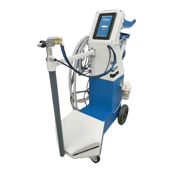
See Figure 2-1. This manual covers all versions of the Encore VT manual powder spray ® systems: • Mobile Dolly System with Vibratory Box Feeder (VBF) • Rail Mount and Wall Mount Systems VBF Mobile Rail/Wall Mount Figure 2-1 Encore VT Manual Powder Systems 1626653-01 © 2024 Nordson Corporation... -
Page 12: System Documentation
Table 2-1 System Documentation Document Component Document Support Summary Part Number System overview, system controls, Encore VT Manual Powder Spray 1626653 troubleshooting, and all information related to System Manual pump controller. Encore VT Dolly Installation Guide 1626649 System installation guide for dolly. -
Page 13: Common Powder Symbols
Electrode Air Wash Flow Air (VT) Flow (HD) Fluidizing Air System Input Air Interconnect Cable Receptable or Network 1 - Power-CAN 2 - LAN 3 - WAN Purge Air Spray Gun or Spray Gun Receptacle 1626653-01 © 2024 Nordson Corporation... -
Page 14: System Components
• Encore system controller • Encore LT manual spray gun and cable • nLighten kit • Encore VT pump controller • Encore Gen II 90-degree powder feed pump • Encore venturi pump pickup tube • Vibratory table and motor − up to 50 lb (25.0 kg) box of powder •... - Page 15 Overview Encore Encore LT System Controller Powder Spray Gun Pump Controller Encore Pump Figure 2-2 Common System Components (Not all system configuration components are shown) 1626653-01 © 2024 Nordson Corporation...
-
Page 16: Encore System Controller
Flow air lifts fluidized powder from a vibratory box feed or a feed hopper and forces the powder through the powder hose to the spray guns. Atomizing air dilutes and atomizes the powder stream, and increases its velocity, as it exits the pump. 1626653-01 © 2024 Nordson Corporation... -
Page 17: Specifications
Encore LT Powder Spray Gun +/− 19 Vac, 1 A 100 kV, 100 µA Encore System Controller 24 Vdc, 0.33 A Encore VT Pump Controller 100−250 Vac, 50/60 Hz, 125 VA 24 Vdc, 2.5 A Vibratory Motor 50 Hz 230 Vac, +/− 10% Vibratory Motor 60 Hz 115 Vac, +/−... -
Page 18: Pump Controller Dimensions
2-8 Overview Pump Controller Dimensions 274 mm 318 mm (10.8 in.) 230 mm (12.5 in.) (9.0 in.) 230 mm (9.1 in.) 375 mm (14.8 in.) Figure 2-3 Encore VT Pump Controller 1626653-01 © 2024 Nordson Corporation... -
Page 19: Powder Spray Gun Certification Label
Overview Powder Spray Gun Certification Label 1600448-05 System Controller Certification Label 1626518 Pump Controller Certification Label 1626519 1626653-01 © 2024 Nordson Corporation... - Page 20 2-10 Overview 1626653-01 © 2024 Nordson Corporation...
-
Page 21: Installation
Wire the system power cord to a customer-supplied three-prong plug. Connect the plug to a receptacle that supplies the correct voltage. Table 3-1 Power Cord Wiring Wire Color Function Blue N (neutral) Brown L (hot) Green/Yellow GND (ground) 1626653-01 © 2024 Nordson Corporation... -
Page 22: System Ground
2. Connect the flat braided ground wire from the system controller ground stud to the grounding block. 3. Connect the flat braided ground cable from the pump controller ground stud to the grounding block. 1626653-01 © 2024 Nordson Corporation... -
Page 23: Operation
Most of the system operation is performed through the system controller. Additional operation information can be found in the applicable component manuals. Refer to System Documentation in the Overview section for a list and links to documentation. 1626653-01 © 2024 Nordson Corporation... -
Page 24: Specific Conditions For Use
4-2 Operation Specific Conditions of Use 1. The Encore VT and HD Manual and Mobile Powder Systems shall be used only with the separately and suitably certified Encore LT Powder Electrostatic Manual Applicators, and Encore HD Powder Electrostatic Manual Applicators in accordance with the manufacturer’s instructions. - Page 25 Operation Fluidizing Air Supply and Ground Connection Pickup Tube Arm Tube Catch Powder Box Pickup Tube Vibrator Table Figure 4-1 Powder Box Installation 1626653-01 © 2024 Nordson Corporation...
-
Page 26: Fluidizing Air Operation
NOTE: Over or under fluidization is a common cause of inconsistent powder delivery. Fluidize the powder for 5−10 minutes to make sure it is evenly fluidized and no clumps are left before spraying. 1626653-01 © 2024 Nordson Corporation... -
Page 27: Electrode Air Wash Operation
Figure 4-2 Electrode Air Wash and Fluidizing Air Valve Location (shown without flow control valve) Flow Control Valve To Spray Gun Electrode Air Wash Connector Figure 4-3 Flow Control Valve and Air Wash Tubing Connection 1626653-01 © 2024 Nordson Corporation... -
Page 28: Daily Operation
• turn OFF after a delay when the trigger is released, or • continue to operate until the system power is turned OFF. Refer to the system controller onscreen Help for information on changing the motor function setting. 1626653-01 © 2024 Nordson Corporation... - Page 29 The system controller displays the setpoints on the Home screen. When the gun is spraying, the actual output appears underneath the setpoints. System Controller Touchscreen Purge Trigger Spray Trigger Power Button Figure 4-4 System Controls 1626653-01 © 2024 Nordson Corporation...
-
Page 30: Shutdown
2. Turn OFF the system air supply and relieve the system air pressure. 3. Press the Power button on the pump controller to turn OFF the system. 4. Perform the appropriate maintenance steps listed in Maintenance Procedures. 1626653-01 © 2024 Nordson Corporation... -
Page 31: Maintenance
Refer to System Documentation in the Overview section for a list and links to documentation. Recommended Cleaning Procedure for Powder Contact Parts Nordson Corporation recommends using an ultrasonic cleaning machine and Oakite® BetaSolv emulsion cleaner to clean spray gun nozzles and powder path parts. CAUTION: Do not immerse the electrode assembly in solvent. -
Page 32: Maintenance Procedures
Check the system air filter. Drain the filter and change the filter element as needed. Refer to Parts for Air Filter the replacement filter element part number. (Periodically) Daily: Make sure the system is securely connected to a true earth ground before spraying powder. System Grounds Periodically: Check all system ground connections. 1626653-01 © 2024 Nordson Corporation... -
Page 33: Troubleshooting
Use safety glasses when performing the following tasks. These troubleshooting procedures cover only the most common problems. If you cannot solve a problem with the information given here, contact Nordson technical support at (800) 433−9319 or your local Nordson representative for help. -
Page 34: System Controller Alarms And Activity Log
Use the onscreen Help and the troubleshooting tables in this section for information regarding individual Alarm and Activity codes. Alarms and Activity Log Help Figure 6-1 Help and Activity Log 1626653-01 © 2024 Nordson Corporation... -
Page 35: Activity Codes Troubleshooting Chart
Check for a shorted gun cable. Check for a bad multiplier using a kV meter and a mega-Ohm meter. 0x2010u Over Current Replace cable if bad. Replace multiplier if bad. Refer to the spray gun manual for repair and parts information. Continued... 1626653-01 © 2024 Nordson Corporation... - Page 36 0x5001u Device DCB EEPROM Fail Replace the device controller. The device controller address should always be 1. If system 0x5003u Device Invalid Node ID malfunctions call Nordson Service for assistance. Continued... 1626653-01 © 2024 Nordson Corporation...
- Page 37 0x5015u Valve Purge Air Check J4 pin 3 and 4 wiring diagram backplane. 0x6000u Device Hw Sw Mismatch Call Nordson Service for assistance. System controller is resetting. Check for proper chassis 0x6100u Watchdog Alarm grounding. Check for powder tribo charging.
-
Page 38: General Troubleshooting Chart
Remove and inspect the nozzle or deflector. Replace worn parts. Remove and clean the electrode assembly. Remove and clean 4. Voids in powder Plugged electrode the spray gun powder path (inlet tube, elbow, and outlet tube) if assembly or powder path necessary. 1626653-01 © 2024 Nordson Corporation... - Page 39 Perform the Gun Cable Continuity Test in spray gun manual. If solenoid valve; no air pressed down the cable is good, replace the trigger switch. pressure, or kinked air tubing Check the purge air tubing and purge manifold solenoid valve. Continued... 1626653-01 © 2024 Nordson Corporation...
- Page 40 13. VBF system− fluidizing air is ON Controller configured for Make sure system controller is configured for a VBF system. when the gun is a hopper system triggered OFF Continued... 1626653-01 © 2024 Nordson Corporation...
-
Page 41: Controller Interconnect Cable Test
J1 - Power Unit End P1 - Interface End (Female) (Female) GROUND SHIELD J1-1 P1-1 +24VDC J1-2 P1-2 DC COM BLACK J1-3 P1-3 CAN-L BLUE J1-4 P1-4 CAN-H WHITE P1-5 J1-5 Figure 6-2 Controller Interconnect Cable Wiring 1626653-01 © 2024 Nordson Corporation... - Page 42 6-10 Troubleshooting 1626653-01 © 2024 Nordson Corporation...
-
Page 43: Repair
Refer to the Drawings section for the pump controller electrical schematic and harness connections. Refer to System Documentation in the Overview section for a list and links to documentation. 1626653-01 © 2024 Nordson Corporation... -
Page 44: Pump Controller
(1). 4. Slowly remove panel assembly CAUTION: Handle cable and connectors with care. When reassembling, do not allow cables or air lines to become pinched or twisted at the back of the enclosure wall. 1626653-01 © 2024 Nordson Corporation... - Page 45 Repair External Enclosure Ground Internal Enclosure Ground Figure 7-2 Panel Removal 1. Enclosure 2. Screws 3. Panel assembly 1626653-01 © 2024 Nordson Corporation...
-
Page 46: Panel Components
(10). 2. Make sure the O-rings furnished with the new valves are in place before installing the new valve on the manifold. Torque screws to 0.16 N•m (1.4 in.-lb). 1626653-01 © 2024 Nordson Corporation... - Page 47 Repair Figure 7-3 Panel Repair 1. Device controller 5. M3 Screw 8. Solenoid valve 2. Latch 6. Electric regulator 9. Screw 3. Harness 7. Cap screw 10. Manifold 4. Mini-backplane 1626653-01 © 2024 Nordson Corporation...
-
Page 48: Power Supply
1. To remove the relay PCA (3), disconnect the terminal wires and remove the four M3 screws (2) to remove relay PCA from panel. 2. When installing new relay PCA, make sure to reconnect wires to their respective terminals on the relay PCA. 1626653-01 © 2024 Nordson Corporation... - Page 49 Relay PCA Terminals Figure 7-4 PCA Relay and Terminal Connections 1. Power supply 2. M3 screw 3. Relay PCA Table 7-1 PCA Relay Terminal Connections Terminal Description Wire Color Brown Neutral Light Blue Ground Green/Yellow 1626653-01 © 2024 Nordson Corporation...
-
Page 50: Vibrator Motor Replacement
See Figure 7-5. When replacing the vibrator motor (1), make sure to order the correct motor for system voltage. Check the label on the vibrator motor. Replacement motors include the power cable (2). Bottom View of Dolly Figure 7-5 Replacing Vibrator Motor 1. Vibrator motor 2. Power cable 1626653-01 © 2024 Nordson Corporation... -
Page 51: Parts
Section 8 Parts Introduction To order parts, call the Nordson Industrial Coating Solutions Customer Support Center at (800) 433-9319 or contact your local Nordson representative. For other system components not listed in this section, refer to the System Documentation in the Overview section. -
Page 52: Encore Vt Manual Powder Spray Systems
VBF Mobile Rail/Wall Mount Figure 8-1 Encore HD Manual Powder Systems Part System Description 1625456 Encore VT 115 V VBF Dolly System 1625458 Encore VT 230 V VBF Dolly System 1625537 Encore VT Wall/Rail Mount System 1626653-01 © 2024 Nordson Corporation... -
Page 53: Pickup Tube Kits
• RETAINING CAP, external, 0.625 OD, push-on, black Filter See Figure 8-1 and the following parts list. Item Part Description Quantity Note 1600608 FILTER, mist separator, 0.3 micron, 1/2 NPT 1600609 FILTER ELEMENT, mist separator, 0.3 micron NS: Not Shown 1626653-01 © 2024 Nordson Corporation... -
Page 54: Pump Controller Kits
8-4 Parts Pump Controller Kits See Figure 8-2 and the following parts lists. Left Rear Panel View Right Rear Panel View Figure 8-2 Pump Controller Panel 1626653-01 © 2024 Nordson Corporation... -
Page 55: Relay Pca
See Figure 8-2 and the following parts lists. Item Description Quantity Note 1626873 - KIT, service, mini-backplane, Encore Mobile System — • SCREW, pan, recess, M3 x 8, with internal lockwasher, black zinc • PCA, mini-backplane, Encore 1626653-01 © 2024 Nordson Corporation... -
Page 56: Manifold Assembly
Figure 8-3 Manifold Assembly Item Description Quantity Note 1625949 - MANIFOLD ASSEMBLY, control, manual, Encore VT — • GASKET, manifold, controller, Encore LT • MUFFLER, exhaust, 1/8 BSPT • VALVE, check, M8 T x R1/8, M input • CONNECTOR, male, with internal hex, 10 mm T x 1/8 unithread •... -
Page 57: Vbf Motor Kits
• VIBRATOR, electric, with molded connector • ISOLATOR, vibrator, 1.0 diameter, x 1.5 x 5/16 studs • NUT, hex, serrated, 5/16-18, steel, zinc • WASHER, lock, M, internal, M6, steel, zinc • SCREW, button, socket, M6 x 20, black 1626653-01 © 2024 Nordson Corporation... -
Page 58: Grounding Equipment
It is conductive and grounds the pickup tube to the cart body. Do not replace with non- conductive tubing. D. Minimum order quantity is 25 ft. E. Minimum order quantity is 100 ft. 1626653-01 © 2024 Nordson Corporation... -
Page 59: Drawings
Drawings Section 9 Drawings Description Part Number Encore VT Manual Gun Controller Wiring Diagram 10022885 1626653-01 © 2024 Nordson Corporation... - Page 60 9-2 Drawings 1626653-01 © 2024 Nordson Corporation...
-
Page 62: Eu Declaration Of Conformity
This Declaration is issued under the sole responsibility of the manufacture. Product: Encore VT and HD Manual and Mobile Powder Systems Models: Encore VT and HD Manual and Mobile Powder Systems with “NEW CONTROLS TECHNOLOGY”. Description: The manual powder electrostatic powder spray system includes applicator, control cable and associate controls. - Page 63 This Declaration is issued under the sole responsibility of the manufacture. Product: Encore VT and HD Manual and Mobile Powder Systems Models: Encore VT and HD Manual and Mobile Powder Systems with “NEW CONTROLS TECHNOLOGY”. Description: The manual powder electrostatic powder spray system includes applicator, control cable and associate controls.
- Page 64 THIS DRAWING IS NORDSON PROPERTY,CONTAINS PROPRIETARY INFORMATION AND MUST BE RETURNED UPON REQUEST. ZONE REV. DESCRIPTION ECO NO. DATE DO NOT CIRCULATE, REPRODUCE OR DIVULGE TO OTHER PARTIES WITHOUT WRITTEN CONSENT OF NORDSON. ISSUED 11OCT23 REVISED PN, WAS 1625570; ADDED INFO/VIEWS ON SHEET 2 17OCT24 RELEASED...
- Page 65 REVISION 10023171 NOTICE THIS DRAWING IS NORDSON PROPERTY,CONTAINS PROPRIETARY INFORMATION AND MUST BE RETURNED UPON REQUEST. DO NOT CIRCULATE, REPRODUCE OR DIVULGE TO OTHER PARTIES WITHOUT WRITTEN CONSENT OF NORDSON. RAIL MOUNT WALL MOUNT SYSTEM CONTROLLER CONFIGURATION FOR WALL/RAIL MOUNT SYSTEMS 1625536 AND 1625537 ENCORE VT 115V 60Hz &...
Need help?
Do you have a question about the Encore VT and is the answer not in the manual?
Questions and answers