Table of Contents
Advertisement
Quick Links
r
Encore
Manual Porcelain Enamel
Powder Spray Systems
Customer Product Manual
Part 1612500−02
Issued 7/18
For parts and technical support, call the Industrial Coating
Systems Customer Support Center at (800) 433-9319 or
contact your local Nordson representative.
This document is subject to change without notice.
Check http://emanuals.nordson.com for the latest version.
NORDSON CORPORATION • AMHERST, OHIO • USA
Advertisement
Table of Contents
Troubleshooting

Related Manuals for Nordson Encore Series


Summary of Contents for Nordson Encore Series
- Page 1 For parts and technical support, call the Industrial Coating Systems Customer Support Center at (800) 433-9319 or contact your local Nordson representative. This document is subject to change without notice. Check http://emanuals.nordson.com for the latest version. NORDSON CORPORATION • AMHERST, OHIO • USA...
- Page 2 Contact Us Notice This is a Nordson Corporation publication which is protected by copyright. Nordson Corporation welcomes requests for information, comments, and Original copyright date 2018. No part of this document may be inquiries about its products. General information about Nordson can be...
- Page 3 Change Record Revision Date Change 02/18 Release 07/18 Updated to add XD electrode support, added nLighten LED inspection kit, added power supply resistance test, revised part number 1106870 description, added system numbers including nLighten systems Part 1612500−02 E 2018 Nordson Corporation...
- Page 4 Change Record Part 1612500−02 E 2018 Nordson Corporation...
-
Page 5: Table Of Contents
....Controller Certification Label ......Part 1612500−02 E 2018 Nordson Corporation... - Page 6 Rear Panel Components ....... 6-16 Part 1612500−02 E 2018 Nordson Corporation...
- Page 7 ......... Part 1612500−02 E 2018 Nordson Corporation...
- Page 8 Table of Contents Part 1612500−02 E 2018 Nordson Corporation...
-
Page 9: Safety
Regulations and Approvals Make sure all equipment is rated and approved for the environment in which it is used. Any approvals obtained for Nordson equipment will be voided if instructions for installation, operation, and service are not followed. All phases of equipment installation must comply with all federal, state, and local codes. -
Page 10: Personal Safety
Clean, maintain, test, and repair equipment according to the instructions in your equipment documentation. Use only replacement parts that are designed for use with original equipment. Contact your Nordson representative for parts information and advice. Part 1612500−02 E 2018 Nordson Corporation... -
Page 11: Grounding
Disconnect and lock out electrical power. Close pneumatic shutoff valves and relieve pressures. Identify the reason for the malfunction and correct it before restarting the equipment. Disposal Dispose of equipment and materials used in operation and servicing according to local codes. Part 1612500−02 E 2018 Nordson Corporation... - Page 12 Safety Part 1612500−02 E 2018 Nordson Corporation...
-
Page 13: System Setup
5. Rail bracket 8. M8 x 70 screws 2. M5 x 12 screws 6. Rail 9. #10 dished lock washer 3. M8 x 40 screws 7. M8 lock washers 10. Parts tray 4. M8 jam nuts Part 1612500−02 E 2018 Nordson Corporation... -
Page 14: System Connections
6mm blue Pump Mount and Power Pickup Tube Supply 10mm Input Air Relay Board Feed Hopper Dolly or Booth Line AC Power Cord Ground Filter Figure 2-2 Encore PE Manual Powder System Block Diagram Part 1612500−02 E 2018 Nordson Corporation... -
Page 15: System Setup And Connections
2. Power cord (15ft) 6. Gun cable 9. Fluidizing air needle valve 3. Atomizing air (blue, 8mm, pump) 7. Purge air (black, 6mm, gun) 10. Electrode air wash (clear, 4mm, gun) 4. Air supply (blue, 10mm) Part 1612500−02 E 2018 Nordson Corporation... -
Page 16: Spray Gun Connections
2. Thread the cable nut onto the receptacle and tighten the nut securely. 3. Secure the cable strain relief to the rear panel with one of the existing panel screws. Mobile System Rail/Wall Mount System Strain Relief Figure 2-4 Gun Cable Connection and Strain Relief Mounting Part 1612500−02 E 2018 Nordson Corporation... -
Page 17: Air Tubing And Powder Hose
The flow control valve can be located anywhere desired. Use a tubing cutter to make sure the tube ends are square. Air Wash Connector Flow Control Valve To Gun 4-mm Tubing Figure 2-6 Flow Control Valve and Air Wash Tubing Connection Part 1612500−02 E 2018 Nordson Corporation... -
Page 18: Pump And Hopper Connections
Tighten the clamp to secure the hose. Route the other end of the vent hose into the spray booth. 10. Refer to Connecting the Powder Hose to the Pump on page 2-8 for instructions. Part 1612500−02 E 2018 Nordson Corporation... - Page 19 9. Ground wire 2. Powder hose 6. Black flow air tubing 10. 10 x 6 mm reducer fitting 3. Vent hose clamp 7. Pump 11. Grommet 4. Blue atomizing air tubing 8. Blue fluidizing air tubing Part 1612500−02 E 2018 Nordson Corporation...
-
Page 20: Connecting The Powder Hose To The Pump
All systems are shipped with a 0.3-micron air filter. It is important that the filter be used to prevent contamination of the system pneumatic components and the powder supply. Supply air pressure should be 4.0−7.6 bar (58−110 psi). Part 1612500−02 E 2018 Nordson Corporation... -
Page 21: Mobile Systems
Air Filter Installation − Wall and Rail Mount Systems 1. 10-mm air tubing (blue) 4. Bracket 6. Release latch 2. 10-mm tube x 1/2 male connectors 5. Flow indicator 7. Customer-supplied fasteners 3. M5 screws Part 1612500−02 E 2018 Nordson Corporation... -
Page 22: System Electrical Connections
A: Auto (refer to troubleshooting to change the jumper if A is displayed) H: Manual 3. The controller software and hardware version are displayed on the KV/μA panel in the form N.NN for 1 second. Part 1612500−02 E 2018 Nordson Corporation... -
Page 23: Entering Configuration Mode
Enable/Disable Select Charger Settings Flow-Rate Air (Classic) Powder Flow Rate (Smart Flow) KV/μA Setting/Display Setting/Display KV/uA Selection Smart Flow Mode Control Indicator Atomizing Air (Classic) Total Flow (Smart Flow) Setting/Display Figure 2-11 Controller Interface Part 1612500−02 E 2018 Nordson Corporation... -
Page 24: Function Settings
NOTE: Refer to the Operation section for explanations of the differences in Electrostatic Control and Powder Flow Control modes. Exiting Configuration Mode To accept all function values and exit Configuration Mode, press the Enable/Disable button. The controller can now be operated normally. Part 1612500−02 E 2018 Nordson Corporation... -
Page 25: Description
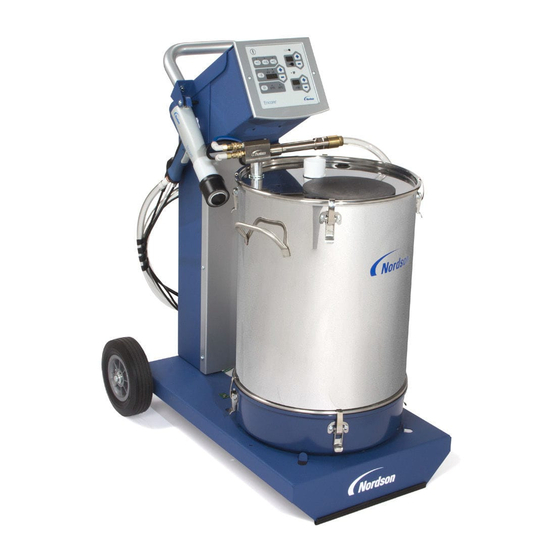
See Figure 3-1. This manual covers all versions of the Encore PE Manual Powder Spray System: Mobile system with feed hopper Rail-mount system Spray Gun Pump Pump Mount Hopper Controller with Rail Mount Installed Mobile System with Feed Hopper Figure 3-1 Encore PE Manual Powder Systems Part 1612500−02 E 2018 Nordson Corporation... -
Page 26: Mobile System Components
This applicator and controller are used with Porcelain Enamel powders which are non-flammable. Mobile System with 50Lb. Feed Hopper Height: 995 mm (35.2 in.) Length: 812 mm (32 in.) Wheel Base: 598.5 mm (23.5 in.) Weight: 51.5 kg (114 lbs) Part 1612500−02 E 2018 Nordson Corporation... -
Page 27: Equipment Labels
Î Î Î Î Î Î Î Î Controller Certification Label ENCORE LT EN 50050 FM11ATEX0057X (2) 3 D Ex tc IIIC T60°C Dc T = +15 to +40°C NORDSON CORP. AMHERST, OH, USA Vn=100−250Vac 7n=50−60Hz Pn=100VA = +19V Io = +1.0A OUTPUT: V (peak) (peak) WARNING −... - Page 28 Description Part 1612500−02 E 2018 Nordson Corporation...
-
Page 29: Operation
The system hibernates automatically if no activity is detected for approximately 15 minutes. Pulling the spray gun trigger, pressing the purge switch, or pressing a button on the controller interface wakes the controller. Part 1612500−02 E 2018 Nordson Corporation... -
Page 30: Displays And Leds
The electrostatic setpoints for the Select Charge Modes are: Re-Coat 100 kV, 15 μA Metallics 50 kV, 50 μA Deep Recesses 100 kV, 60 μA NOTE: Pressing the + or − keys have no effect when a Select Charge mode is selected. Part 1612500−02 E 2018 Nordson Corporation... -
Page 31: Custom Electrostatic Mode
μA. Press the + or − buttons to select the desired kV setpoint. The longer a button is pressed the faster the units change. The valid STD range is 0 or 25−100 kV. Part 1612500−02 E 2018 Nordson Corporation... -
Page 32: Classic Afc Mode
For example, the user can set the kV settings from 25, 24, 23, 22, ….. through 0. NOTE: kV and μA will now allow the user to adjust the kV independently of μA when below the value of 25 kV. Part 1612500−02 E 2018 Nordson Corporation... -
Page 33: Powder Flow Settings
Classic Flow mode, the Smart Flow LED is off. NOTE: Refer to page 2-11 for a list of the mode defaults and configuration instructions. Flow Air % or Flow Air Total Flow or Atomizing Air Figure 4-4 Flow Setting Panels Part 1612500−02 E 2018 Nordson Corporation... -
Page 34: Smart Flow Mode Settings
Powder velocity is inversely related to transfer efficiency; the higher the velocity, the lower the transfer efficiency. High powder flow rates can result in faster wear of the powder contact parts. Part 1612500−02 E 2018 Nordson Corporation... -
Page 35: Classic Flow Mode Settings
If Flow air = 40%, Atomizing = 10%, then Flow air = 2.7 bar (40 psi), Atomizing air = 0.689 bar (10 psi). Refer to your pump manual for typical operating values for Flow and Atomizing air. Part 1612500−02 E 2018 Nordson Corporation... -
Page 36: Spray Gun Operation
Fluidizing air is on continuously as long as the controller is 7. Point the spray gun into the booth and press the trigger to start spraying powder. Part 1612500−02 E 2018 Nordson Corporation... -
Page 37: Purging
3. Turn off the system air supply and relieve the system air pressure. 4. If shutting down for the night or a longer period of time, disconnect power to the controller. 5. Perform the Daily Maintenance procedures on page 4-13. Part 1612500−02 E 2018 Nordson Corporation... -
Page 38: Maintenance
Refer to Electrode Support Assembly Replacement in the Repair section of this manual. 4. Clean all parts with low-pressure compressed air. Inspect all parts and replace any that are worn or damaged. Part 1612500−02 E 2018 Nordson Corporation... - Page 39 2. Deflector 5. Nozzle nut 8. Electrode support assembly (XD shown) 3. Pattern adjuster 6. Electrode holder (See Note) Note: The electrode holder used on Conical Spray Nozzles are not interchangeable with Flat/Corner spray nozzles. Part 1612500−02 E 2018 Nordson Corporation...
-
Page 40: Cleaning Flat And Corner Spray Nozzles
2. Nozzle (flat spray shown) 4. Electrode holder (See Note) 6. Electrode support assembly (XD shown) Note: The electrode holder used on a Flat/Corner spray nozzle is not interchangeable with a Conical spray nozzle. Part 1612500−02 E 2018 Nordson Corporation... -
Page 41: Daily Maintenance
Check the system air filter. Drain the filter and change the filter element as needed. Refer to Parts for the replacement element part number. Check all system ground connections. Part 1612500−02 E 2018 Nordson Corporation... - Page 42 Operation 4-14 This page intentionally left blank. Part 1612500−02 E 2018 Nordson Corporation...
-
Page 43: Troubleshooting
These troubleshooting procedures cover only the most common problems. If you cannot solve a problem with the information given here, contact your contact Nordson technical support at (800) 433−9319 or your local Nordson representative for help. Controller Faults... -
Page 44: General Troubleshooting Chart
Replace worn parts. pattern Plugged electrode assembly or Remove and clean the electrode powder path assembly. Remove and clean the spray gun powder path (inlet tube, elbow, and outlet tube) if necessary. Continued... Part 1612500−02 E 2018 Nordson Corporation... - Page 45 Orifice size is .25−.3 mm. Clean with an appropriate tool. Continued... Part 1612500−02 E 2018 Nordson Corporation...
- Page 46 Flow Air or Total Flow set to zero Change settings to a non-zero 11. No powder flow when number. gun is triggered On, kV OK Input air turned OFF Make sure air is being supplied to the controller. Part 1612500−02 E 2018 Nordson Corporation...
- Page 47 The cable should be inserted past the white line marked towards the end of the cable. Push the black bar back into the white connector to secure. Part 1612500−02 E 2018 Nordson Corporation...
-
Page 48: Spray Gun Power Supply Resistance Test
C or 72 F. Allow time for the multiplier to cool to room temperature for repeatable results. 225-335 Megohms at 500 VDC J2−3 (YELLOW) J2−1 (RED) FEEDBACK J2−2 (BLACK) COMMON Figure 5-8 Power Supply Resistance Test Part 1612500−02 E 2018 Nordson Corporation... -
Page 49: Electrode Support Resistance Test
The resistance should be 19−21 megohms. If the resistance is out of this range replace the electrode assembly. 19−21 Megohms Figure 5-9 Electrode Support Resistance Test Part 1612500−02 E 2018 Nordson Corporation... -
Page 50: Gun Cable Continuity Test
(N/C) J1−1 J1−3 J3−2 J3−4 (ORANGE) (RED) (ORANGE) (WHITE) J3−3 (GREEN) J2−1 J2−3 J1−6 (RED) J1−4 (YELLOW) J2−2 (GREEN) (WHITE) (BLACK) J1−5 J2 (FACE VIEW) (YELLOW) POWER SUPPLY CONNECTOR Figure 5-10 Gun Cable Wiring Part 1612500−02 E 2018 Nordson Corporation... -
Page 51: Repair
Power Supply Trigger Connectors Connectors Figure 6-1 Gun Disassembly 28. Housing cover 30. Hook 31B. M3 x 20 screw 29. Display housing 31A. M3 x 30 screw Part 1612500−02 E 2018 Nordson Corporation... - Page 52 Figure 6-2 Removing the Gun Body from the Handle 20. Gun body 22. Powder outlet tube 44. Black nylon M5 screw 20A. Air wash tubing (filter assembly) 40. Handle Part 1612500−02 E 2018 Nordson Corporation...
-
Page 53: Power Supply Replacement
3. Pull the base away from the handle, swing the bottom of the ground pad (27) up and away from the handle, then remove it. Leave the ground wire connected to the ground pad. Part 1612500−02 E 2018 Nordson Corporation... -
Page 54: Powder Path Installation
(27) into the body and rotate it onto the handle. Make sure the cable wires are not pinched or trapped during re-assembly. 4. Install the handle base onto the handle and ground pad and secure it with the two M3 x 20 screws (31B). Part 1612500−02 E 2018 Nordson Corporation... -
Page 55: Gun Reassembly
While pushing the body and handle together, use your finger to make sure the end of the outlet tube fits into the hole in the front of the gun body. Part 1612500−02 E 2018 Nordson Corporation... -
Page 56: Changing From Conical To Flat Or Corner Spray Nozzle
(7, 8, 10, and 11) into the spray gun. 9. Install the flat spray or corner spray nozzle (9) into the new nozzle nut (5), then install the nozzle nut on the spray gun. Part 1612500−02 E 2018 Nordson Corporation... -
Page 57: Cable Replacement
5. Pull the bottom edge of the ground pad out and away from the handle. 6. See Figure 6-7, View B. Remove the M3 x 6 screw (25), lock washer (26), and ground terminal from the ground pad. 7. Remove the E-ring (32) from the cable. Part 1612500−02 E 2018 Nordson Corporation... - Page 58 Trigger Ground VIEW C VIEW B VIEW A Figure 6-7 Cable Replacement 25. M3 x 6 screw 27. Ground pad 32. E-ring 26. M3 lock washer 31B. M3 x 20 screws 39. Handle base Part 1612500−02 E 2018 Nordson Corporation...
-
Page 59: Cable Installation
(41A) and lightly tap to remove. 5. Remove the spray trigger (41), actuator (42, not shown), and purge trigger (43) from the handle. Gusset Figure 6-8 Removing the Axle and Trigger from the Handle Part 1612500−02 E 2018 Nordson Corporation... -
Page 60: Switch Installation
Figure 6-10 Installing the Trigger Switch − Steps 1 and 2 3. See Figure 6-11. Straighten the ribbon cable, then bend the pull tab at the top of the switch so that it is perpendicular to the switch. Part 1612500−02 E 2018 Nordson Corporation... - Page 61 6. Make sure the ribbon cable is not trapped or pinched, then press the switch against the back of the recess. Run your finger up and down on the switch to ensure it is securely adhered to the handle. Part 1612500−02 E 2018 Nordson Corporation...
- Page 62 10. Reconnect the trigger switch connector to the round cable connector, then tuck the connectors back up to the handle. 11. Reinstall the ground cover as described in Cable Installation steps 5−7 on page 6-9. Part 1612500−02 E 2018 Nordson Corporation...
-
Page 63: Electrode Support Assembly Replacement − Xd Version
3. Install the electrode into the electrode holder, then screw the electrode holder into the ceramic spider. Figure 6-14 XD Electrode Support Assembly Replacement 1. Electrode holder 3. O-ring 4a. Ceramic spider 2. Electrode 4. Electrode support assembly 4b. PU seal Part 1612500−02 E 2018 Nordson Corporation... -
Page 64: Electrode Support Assembly Replacement − Sd Version
8. Install the electrode into the electrode holder, then screw the electrode holder into the spider. Alignment Holes for Spring Alignment Keyways Figure 6-15 Electrode Support Sleeve Replacement 1. Electrode holder 3. Spider 5. Spring 2. Electrode 4. Sleeve 6. Electrode support assembly Part 1612500−02 E 2018 Nordson Corporation... -
Page 65: Controller Repair
Refer to Section 5, Troubleshooting, for the controller electrical schematic and harness connections. Refer to Section 7, Parts for repair kits. Figure 6-16 Controller Front Panel 1. Bezel 2. Keypad 3. Main control board Part 1612500−02 E 2018 Nordson Corporation... -
Page 66: Rear Panel Components
1. Manifold assembly 4. Line filter 7. Air wash air solenoid valve 2. Relay board 5. Fluidizing air solenoid valve 8. Flow-rate air regulator 3. Power supply 6. Purge air solenoid valve 9. Atomizing air regulator Part 1612500−02 E 2018 Nordson Corporation... -
Page 67: Parts
Parts Section 7 Parts Introduction To order parts, call the Nordson Industrial Coating Systems Customer Support Center at (800) 433-9319 or contact your local Nordson representative. This section covers parts for the Encore PE spray gun, controller, system components and parts, powder and air tubing, and options. -
Page 68: Spray Gun
Parts Spray Gun Figure 7-18 Spray Gun Part 1612500−02 E 2018 Nordson Corporation... - Page 69 S CHECK VALVE, male, M5 x 6 mm tube 1081616 S FITTING, bulkhead, barbed, dual, 10−32 x 4 mm tubing 1087762 S BASE, handle, spray gun, Encore 1106870 S HANDLE, spray gun, Encore LT/PE Continued... Part 1612500−02 E 2018 Nordson Corporation...
- Page 70 B: Refer to Figure 7-20 and parts list for repair parts for the optional SD Electrode Support Assembly kit. C: Refer to Powder Hose and Air Tubing on page 7−11 for minimum order quantities. Part 1612500−02 E 2018 Nordson Corporation...
-
Page 71: Electrode Support Assemblies
S S SPRING, compression, 0.088 OD x 0.75 long 1602192 S KIT, electrode support, Encore PE 1601428 S SPIDER, ceramic, Encore PE NOTE A: SD Electrode Support Assembly is sold as an optional repair part. Part 1612500−02 E 2018 Nordson Corporation... -
Page 72: Spray Gun Options
1601748 1601749 6 mm Corner Spray Nozzle 4 mm Corner Spray Nozzle 1602194 1601431 Flat Spray Electrode Holder Kit Nozzle Nut Electrode Electrode Holder Wear Sleeve Figure 7-21 Optional Flat and Corner Spray Nozzles Part 1612500−02 E 2018 Nordson Corporation... -
Page 73: Controller Parts
Parts Controller Parts Front Panel and Internal Cabinet Ground Parts Illustration Rear Panel Assembly See Figures 7-23 and 7-24 for parts Figure 7-22 Controller Parts Part 1612500−02 E 2018 Nordson Corporation... -
Page 74: Front Panel And Internal Cabinet Ground Parts List
S NUT, hex, M5, brass 983401 S WASHER, lock, split, M5, steel, zinc 983021 S WASHER, flat, 0.203 x 0,406 x 0.040, brass 933469 S LUG, 90, double, 0.250, 0.438 in. 240674 S TAG, ground Part 1612500−02 E 2018 Nordson Corporation... -
Page 75: Rear Panel Parts Illustration
Parts Rear Panel Parts Illustration Manifold Assembly See Figure 7-24 (this screw only) Figure 7-23 Rear Panel Parts Part 1612500−02 E 2018 Nordson Corporation... -
Page 76: Rear Panel Parts List
S SCREW, pan head, recessed, M3 x 8, with lockwasher, black 1107696 S FILTER, line, RFI power, 3A, with 0.250 QD 1606835 S KIT, PCA, relay board, Encore LT−HD 1107695 S POWER SUPPLY, 24VDC, 60W Part 1612500−02 E 2018 Nordson Corporation... -
Page 77: Manifold Illustration And Parts List
1604486 S VALVE, flow control, 6 mm x 1/8 unithread 1108313 S MUFFLER, exhaust, R1/8 1107593 S GASKET, manifold, controller, Encore LT 1107597 S REGULATOR, electro-pneumatic 1099281 S VALVE, solenoid, 3 port, 24V, 0.35W Part 1612500−02 E 2018 Nordson Corporation... -
Page 78: System Components And Parts
Tubing, poly, spiral cut, 0.62 in. ID 301841 Strap, Velcro, w/buckle, 25 x 3 cm NOTE A: Minimum order quantity is 50 ft. (15.24 m). E: Powder feed hose. Minimum order is 25 ft. (7.62 m). Part 1612500−02 E 2018 Nordson Corporation... -
Page 79: System Options
LED inspection kit that helps powder coaters improve quality by effectively illuminating hard to see surface areas. Any imperfection or missed area is quickly identified and corrected. Find out more at: nordsoncoating.com/nLighten. 1611977 nLighten Figure 7-25 LED Inspection Kit Part 1612500−02 E 2018 Nordson Corporation... - Page 80 Parts 7-14 This page intentionally left blank. Part 1612500−02 E 2018 Nordson Corporation...
-
Page 81: Wiring Diagram
Wiring Diagram Section 8 Wiring Diagram Part 1612500−02 E 2018 Nordson Corporation... - Page 82 Wiring Diagram Part 1612500−02 E 2018 Nordson Corporation...
- Page 83 JUMPER 3) (GROUND JUMPER 1) NO.2 6 (GREEN) GROUND (GREEN/YELLOW) RECEPTACLE NO.3 A.C. POWER HARNESS NO.1 (GROUND JUMPER 2) 15 FT (4.6M) POWER CORD CONTROLLER CABINET NO.4 Figure 7-1 Encore LT Manual Controller Wiring Diagram Part 1612500−02 E 2018 Nordson Corporation...
- Page 84 Wiring Diagram This page intentionally left blank. Part 1612500−02 E 2018 Nordson Corporation...
Need help?
Do you have a question about the Encore Series and is the answer not in the manual?
Questions and answers