Table of Contents
Advertisement
Advertisement
Table of Contents

Related Manuals for IFM DTE102


Summary of Contents for IFM DTE102
- Page 1 Device Manual RFID evaluation unit DTE102...
-
Page 2: Table Of Contents
Contents 1 Preliminary note . . . . . . . . . . . . . . . . . . . . . . . . . . . . . . . . . . . . . . . . . . . . . . . . . . . . . . . . . . . . . . . . . . . .4 1 .1 Symbols used . - Page 3 9 .13 Assembly 100 structure . . . . . . . . . . . . . . . . . . . . . . . . . . . . . . . . . . . . . . . . . . . . . . . . . . . . . . . .34 9 .14 Assembly 101 structure .
-
Page 4: Preliminary Note
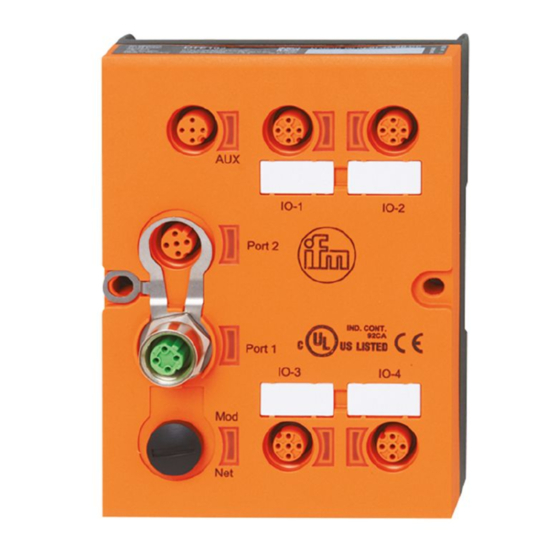
3 Functions and features The RFID evaluation unit DTE102 integrates an EtherNet/IP interface and 4 channels for the connection of field devices . Each channel can be used either for the connection of an RFID antenna or as input/ output to IEC 61131 . -
Page 5: Function
3: Read/write head type ANT51x / ANT41x 4: RFID tag The evaluation unit DTE102 processes data from up to 4 RFID read/write heads (type ANT51x/ANT41x) or IEC 61131 inputs / outputs . The mode of operation for each port can be set individually via the EtherNet/IP master . -
Page 6: Aux" Voltage Supply
The evaluation unit has to be disconnected before field units are connected . Please note that the total current consumption of the device must not exceed the value of 3 A . You can find information about the matching read/write heads on our website at: www .ifm .com... -
Page 7: Allowed Network Infrastructures
4.2 Allowed network infrastructures Linear structure: Ring structure: Star structure: Switch Switch Switch 5 Installation You can find information about installation and electrical connection in the operating instructions for the unit at: www .ifm .com... -
Page 8: Operating And Display Elements
6 Operating and display elements 6.1 Reset to factory settings The Ethernet parameters can be reset to the factory settings . Take the following steps: ► Remove all cable connections from the device . ► Insert an electrically conductive bridge between pin 1 and pin 3 on the process connection IO-3 . ►... -
Page 9: Led Net (Network Status)
LED red LED green Status Note Software error, hardware error of the device Major error Restart the device . If the error still exists, return the device . Flashing Flashing Self-test Starting phase of the device 6.2.4 LED Net (network status) LED red LED green Status... -
Page 10: Special Device- Led Indications
Use with RFID read/write heads LED green LED yellow Status Note Interface in EtherNet/IP master not Interface deactivated configured Flashes at 2 Hz Interface activated, antenna off Interface activated, tag not in the field Interface activated, tag in the field Overload, short-circuit or communication Flashes at 8 Hz Flashes at 8 Hz... -
Page 11: Web Server
8 Web server The unit is equipped with an integrated web server that allows to ● configure the IP settings of the unit ● update the firmware The settings are made via a web browser, e .g . Microsoft Internet Explorer® as from V7 .0 ►... -
Page 12: Tab "Home
8.2 Tab "Home" This is the main menu from where all functions of the evaluation unit can be accessed . Additionally the Ethernet/IP EDS file of the RFID evaluation unit can be downloaded to configure the device within a PLC . -
Page 13: Tab "Network
8.3 Tab "Network" This menu allows to change various Ethernet interface settings of the evaluation unit . Consult your network administrator which settings are necessary to integrate the device into the existing network . If the evaluation unit is directly connected with the PC a static IP address setting is recommended . (→... -
Page 14: Tab "Firmware
This menu allows to update the firmware of the evaluation unit . ► Open the “Firmware” tab on the browser interface . ► Choose firmware file DTE102 .nxf and commit via button [transfer] Do not interrupt power or disconnect cables from the system while the firmware transfer is in... -
Page 15: Tab "Io-Port
8.5 Tab "IO-Port" This menu allows to configure the IO-Ports of the evaluation unit . Each IO-channel can be configured to mode „Inactive“, „Input“, „Output“ and „RWH“ . Mode Function Inactive No function, inactive Input IEC 61131 input Output IEC 61131 output RFID read/write head (Type ANT4xx or ANT5xx) - Page 16 “Data hold time” define how long the RFID data are kept stable . This is helpful if the time interval, in which the RFID tag data are available, is shorter than the host can read these from the RFID unit . “Number of blocks”...
-
Page 17: Tab "Monitor
8.6 Tab "Monitor" This menu shows the data of each port which is detected by the evaluation unit . In this example the IO-1 port is configured as RFID read/write head, IO-2 port as input, IO-3 port as output and IO-4 port as inactive . ►... -
Page 18: Read/Write Head Information
8.6.1 Read/write head information This menu shows the following information about the selected read/write head: ● Article number ● Device type ● Hardware version ● Firmware version ● ID link software ● Production date Button Function Remark Update Go to menu “Antenna firmware” - Back Return to the main menu... -
Page 19: Antenna Firmware
8.6.2 Antenna firmware This menu allows to update the firmware of the Read-/Write head connected at the selected port . ► Open the “Firmware” tab on the browser interface . ► Choose firmware file "xxx .afw" and submit via button [Transfer] . Do not interrupt power or disconnect cables from the system while the firmware transfer is in progress . - Page 20 If the firmware update fail or the Read-/Write head is not detected by the evaluation unit at the selected IO-port, the Read-/Write head is accessible via web browser and the following URL: http://<IP-ADDRESS>/rwhupdate?ioport=<IO-CHANNEL>1&anttype=<ANTENNA_TYPE> &fwVersion= <NUMBER>&setLng=<LANGUAGE> Parameter name Description Remark IP-ADDRESS IP address of the evaluation unit [XXX .XXX .XXX .XXX] IPV4 address IO-CHANNEL...
-
Page 21: Tag Monitoring
8.6.3 Tag monitoring This menu allows to: ● read the UID from the tag ● read from or write to the user data area of the tag 8.6.4 Reading from the tag The UID data is displayed in real time with an update interval of approximately 0,5 seconds . ►... -
Page 22: Writing To The Tag
8.6.5 Writing to the tag ► Click to write to the User data area of the tag . The data length to be written can be set from 1 . . .240 bytes . The address offset can be set from 0 bytes up to the last accessible address of the tag . -
Page 23: Tab "System
8.7 Tab "System" This menu allows to define a password to protect the evaluation unit against unauthorised access To enable the password protection the button "New settings" has to be set to "on" . Parameter Setting Note Username admin User name could not be changed Old password XXXXXX Default password is "admin"... -
Page 24: Tab "Sntp
8.8 Tab "SNTP" If an SNTP server is present in the Ethernet network the internal clock of the evaluation unit can be synchronized with the external time server . ► Click [Submit] to transfer the settings to the evaluation unit . -
Page 25: Tab "Info
8.9 Tab "Info" This menu shows the following information about the evaluation unit: ● Power supply state ● Temperature ● System time ● System date ● Production parameters For a proper operation of the evalution unit the "Power Supply State" should show as "fully operable"... -
Page 26: Tab "Reset
8.10 Tab "Reset" This menu allows the user to reset the evaluation unit remotely . If the device is reset all connections are closed and the outputs are switched off . ► To reset the evaluation unit, check "Please confirm you want to reset the device" . ►... -
Page 27: Configuration
To determine the MAC adress of the device several options are available . 1 . Finding the MAC address on the type label The type lable is located on top of the device above the AUX connector . MAC-ID 00:01:23:45:67:89 DTE102 ifm electronic 45128 Essen Germany DTELF/HFABRWEIUS00 www.ifm.com... - Page 28 3 . Finding the MAC address via the integrated webserver The MAC address is located on the "Network" tab below the hardware information . 4 . Reading the MAC address via the EtherNet/IP Ethernet link object The Ethernet link object, 0xF6, instance 2, attribute 3 returns the MAC address of the device with a length of 6 Bytes .
-
Page 29: Connection Concept Of The Ethernet Interface
9.3 Connection concept of the Ethernet interface The device can be connected to two Ethernet lines, one for each of the connectors "Port 1" and "Port 2" . The integrated Ethernet switch allows to build a line structure, an external switch is not required . The device only has one MAC address, enabling the system to address the evaluation unit with a single IP address . -
Page 30: Number Of The Cip Connections
9.8 Number of the CIP connections Connection type Number Access IO-Messaging 1 * Exclusive Owner (Multicast) 2 * Listen Only Table 5: Number of CIP connections 9.9 RUN/IDLE flag functionality When establishing the connection between the EtherNet/IP scanner and the evaluation unit the 32 Bit realtime header is exchanged via the EtherNet/IP connection manager . -
Page 31: Coding Of The Channel Configuration
9.11.1 Coding of the channel configuration All 4 channels IO-1 . . .IO-4 of the evaluation unit are configured identically . The following table shows the coding of the 8 bytes per channel: Byte Content Remark Channel IO-x number Used to identify the channel within the configuration assembly (CN) [ 01h …... -
Page 32: Examples Of Configuration Data For The Configuration Assembly 102
9.12 Examples of configuration data for the configuration assembly 102 9.12.1 Channel-related configuration Byte 0 …7 per channel Function Channel 1 is set as "inactive" . Table 12: Channel configuration module "Inactive" Byte 0 …7 per channel Function Channel 4 is set as "INPUT" . ●... -
Page 33: Overall Configuration
9.12.2 Overall configuration Example 1: Channel 1 . . .4 configured as RFID read-/write channels Channel IO-1 Channel IO-2 Channel IO-3 Channel IO-4 Function RFID RFID RFID RFID Data hold time 10 ms 10 ms 10 ms 10 ms Data block length 8 bytes 8 bytes 8 bytes... -
Page 34: Assembly 100 Structure
9.13 Assembly 100 structure The assembly 100 (output, consumer) is used to transfer the output data for the channels IO-1…IO-4 to the evaluation unit . The data length of each channel is fixed to 20 bytes (10 words) . Inactive channels or unused data fields should be filled with the default value 0x00 by the PLC . -
Page 35: Module Description
10 Module description The following functions are available: ● Detection if an ID tag is in front of the Read-/Write head . ● Control of Read-/Write head to switch on or off the RFID antenna field . ● Read of the Unique Identifier number (UID) of the ID tag . ●... -
Page 36: Module "Inactive
10.1 Module “Inactive” This module allows the user to: ● switch off an unused process interface IO-1 … IO-4 ● read the diagnostic information of the evaluation unit PLC process data output image (Module Inactive) Byte no . 0x00 0x00 . - Page 37 Description byte 1, “Status byte”: Value Description Remark DR-RDY Reading not started or evaluation unit diagnostics data not ready Diagnostics read ready Diagnostics read response from evaluation unit is ready and available in byte 2 … n . Diag No diagnostics available . evaluation unit diagnostics occurred Data not yet written in the response buffer .
-
Page 38: Module "Input
10.2 Module “Input” This module allows the user to ● read the binary inputs of the process interface IO-1 … IO-4 . ● read the diagnostic information of the evaluation unit . PLC process data output image (Module Input) Byte no . 0x00 0x00 . - Page 39 Description byte 1, “Status byte”: Value Description Remark C/Qi Input at C/Qi < 8 V The level of C/Qi is measured by hardware Input at C/Qi > 11 V The level of C/Qi is measured by hardware Input I/Q < 8 V The level of I/Q is measured by hardware Input I/Q >...
-
Page 40: Module "Output
10.3 Module “Output” This module allows the user to ● read the binary inputs of the process interface IO-1 … IO-4 . ● write to binary outputs of the process interface IO-1 … IO-4 . ● read the diagnostic information of the evaluation unit . PLC process data output image (Module Output) Byte no . - Page 41 Description byte 1, “Status byte”: Value Description Remark C/Qi Level at C/Qo = L The level of C/Qi is not measured, but taken from the output value C/Qo Level at C/Qo = H The level of C/Qi is not measured, but taken from the output value C/Qo Input I/Q <...
-
Page 42: Module "Rwh_Rw", General Description
10.4 Module “RWH_RW”, general description This module allows the user to ● read the UID of the ID tag over the Read-/Write head at process interface IO-1 … IO-4 . Two different modes are available: – Read UID once on request (Synchronous mode) . –... - Page 43 Description Byte 2…20, ”Data byte 1…19”: Dependent on the selected mode this data memory contains command data to send to the evaluation unit . Default value “Control byte”: 0x00 Mode: Read UID automatically, antenna field on PLC process data input image (Module RWH_RW) Byte no .
-
Page 44: Module "Rwh_Rw", Read Uid Of The Id Tag Synchronously
10.5 Module “RWH_RW”, Read UID of the ID tag synchronously In this mode the UID of the ID tag can be read once by setting the bit RD from 0 to 1 . This mode is suitable if the user knows when the ID-tag is present in front of the Read-/Write head . The read UID is kept in the data bytes 2…18 stable while bit RD is set to 1 . - Page 45 Description Byte 1, “Status byte”: Value Description Remark No ID tag detected in front of the Read-/ Write head ID tag is detected in front of the Read-/ Bit is set to 1 as long as the ID tag is detected by the Write head R/W head .
-
Page 46: Module "Rwh_Rw", Read Uid Of The Id Tag Asynchronously
10.6 Module “RWH_RW”, Read UID of the ID tag asynchronously In this mode the UID of the ID tag can be read automatically without sending any read request . This mode is suitable if the user do not know when the ID tag is present in front of the Read-/Write head . Additionally this mode allow the fastest detection of ID-tag cause no command request need to be send to the evaluation unit . - Page 47 Description Byte 1, “Status byte”: Value Description Remark No ID tag detected in front of the Read-/ Write head ID tag is detected in front of the Read-/ Bit is set to 1 as long as the ID tag is detected by the Write head R/W head .
-
Page 48: Module "Rwh_Rw", Read User Data Of The Id Tag Synchronously
10.7 Module “RWH_RW”, Read User data of the ID tag synchronously In this mode the User data of the ID tag can be read edge controlled by setting the bit RD from 0 to 1 . This mode is suitable if the user know when the ID-tag is present in front of the Read-/Write head . The read User data is kept in the data bytes 2…18 stable while bit RD is set to 1 . - Page 49 PLC process data input image (Module RWH_RW) Byte no . DR-RDY Diag EA=0 UD=1 RD-RDY Read data length Read data byte 1 Read data byte 2 . . . Read data byte 16 0x00 0x00 Description Byte 1, “Status byte”: Value Description Remark...
-
Page 50: Module "Rwh_Rw", Read User Data Of The Id Tag Asynchronously
10.8 Module “RWH_RW”, Read User data of the ID tag asynchronously In this mode the User data of the ID tag can be read automatically without sending any read request . This mode is suitable if the user know when the ID-tag is present in front of the Read-/Write head . Additionally this mode allow the fastest detection of ID-tag cause no command request need to be send to the evaluation unit . - Page 51 PLC process data input image (Module RWH_RW) Byte no . DR-RDY Diag UD=1 RD-RDY Read data length Read data byte 1 Read data byte 2 . . . Read data byte 16 0x00 0x00 Description Byte 1, “Status byte”: Value Description Remark No ID tag detected in front of the Read-/...
-
Page 52: Module "Rwh_Rw", Write User Data Of The Id Tag
10.9 Module “RWH_RW”, Write User data of the ID tag In this mode the User data of the ID tag can be written . PLC process data output image (Module RWH_RW) Byte no . DR (3) UR=1 (1) WR (2) AO=0 Write data length 16 bit start address [D15…D8]... - Page 53 PLC process data input image (Module RWH_RW) Byte no . DR-RDY Diag UD=1 WR-RDY Write data length 0x00 . . . 0x00 Description Byte 1, “Status byte”: Value Description Remark No ID tag detected in front of the Read-/ Write head ID tag is detected in front of the Read-/ Bit is set to 1 as long as the ID tag is detected by the Write head...
-
Page 54: Module "Rwh_Rw", Write Verified User Data Of The Id Tag
10.10 Module “RWH_RW”, Write verified User data of the ID tag In this mode the User data of the ID tag can be written and read back with one command request . In the first step the command data is written to the ID tag, in the second step it is read back from the ID tag . - Page 55 PLC process data input image (Module RWH_RW) Byte no . DR-RDY Diag UD=1 RD-RDY WR-RDY Write data length 0x00 . . . 0x00 Description Byte 1, “Status byte”: Value Description Remark No ID tag detected in front of the Read-/ Write head ID tag is detected in front of the Read-/ Bit is set to 1 as long as the ID tag is detected by the...
-
Page 56: Restart Of The Evaluation Unit
10.11 Restart of the evaluation unit The evaluation unit can be remotely restarted . The device shut off the fieldbus interface and the IO ports and execute than a power on cycle . The command can be executed in all modules . The control and status byte must have value 0x0 before the command is started . - Page 57 Description Byte 2: 0x0 . . 0xFF Actualized restart delay time [ms*10] . Value is decremented from “Restart delay time” set in Control byte to 0x0 . After that, the restart sequence is executed . Description Byte 3…20: Not used . Set to default value 0x0 by the evaluation unit .
-
Page 58: Error Codes Of The Evaluation Unit
11 Error codes of the evaluation unit Error codes are signaled with bit “Diag” within the status byte of the response data of the evaluation unit . If more diagnostic events are available, the channel can transfer up to 4 diagnostics simultaneously . The hardware diagnostic events, which are device relevant, are indicated by the Diag bit on all channels . -
Page 59: Error Group Communication User - Evaluation Unit (F5Fe )
Evaluation unit F4FE9005 Wire break on the read/write head Evaluation unit F4FE9006 Upper limit reached at output driver . Evaluation unit F4FE9007 Undervoltage at C/Qo detected Evaluation unit F4FE9008 General read/write head error detected Evaluation unit F4FE9009 Read/write head communication error Evaluation unit F4FE900A I²C communication error (internal error) -
Page 60: List Of Abbreviations
EtherNet/IP Emergency system Web server with reduced functionality to download the firmware of the evaluation unit evaluation unit RFID Identification unit DTE102 Explicit Messaging Acyclic data exchange between I/O scanner and I/O adapter based on TCP/IP communication . Hexadecimal Numeral format, which use 16 values to represent a numeric value: 0 . .9, A, B, C, D, E, F...
Need help?
Do you have a question about the DTE102 and is the answer not in the manual?
Questions and answers