Table of Contents
Advertisement
Quick Links
Advertisement
Table of Contents

Subscribe to Our Youtube Channel
Related Manuals for IFM DTE105


Summary of Contents for IFM DTE105
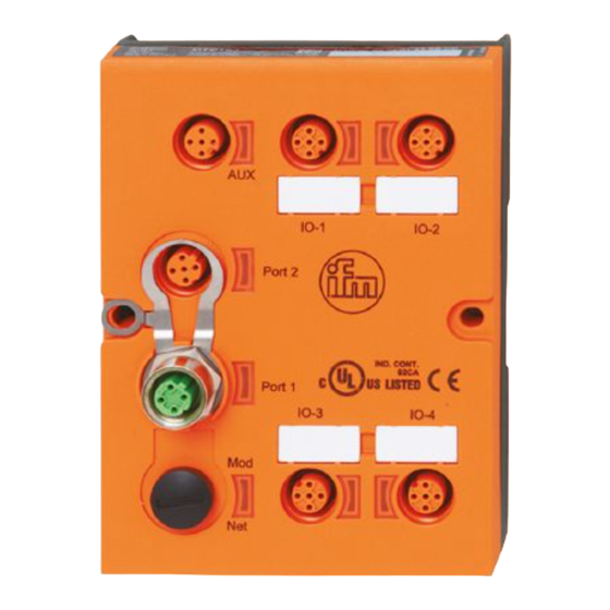
- Page 1 Operating instructions RFID evaluation unit DTE105...
-
Page 2: Table Of Contents
Content 1 Preliminary note ���������������������������������������������������������������������������������������������������4 1�1 Symbols used ������������������������������������������������������������������������������������������������4 1�2 Warnings used �����������������������������������������������������������������������������������������������4 1�3 Copyright and trademarks �����������������������������������������������������������������������������4 2 Safety instructions �����������������������������������������������������������������������������������������������4 3 Functions and features ����������������������������������������������������������������������������������������5 3�1 Configuration via Ethernet interface ��������������������������������������������������������������6 3�2 RFID antennas ����������������������������������������������������������������������������������������������6 4 Items supplied������������������������������������������������������������������������������������������������������6 5 Function ���������������������������������������������������������������������������������������������������������������6 6 Installation������������������������������������������������������������������������������������������������������������7 6�1 Installation distance ���������������������������������������������������������������������������������������7... - Page 3 8�2�6 Special device LED indications ����������������������������������������������������������18 9 Technical data ����������������������������������������������������������������������������������������������������18 9�1 Data sheets �������������������������������������������������������������������������������������������������18 9�2 Device manual ���������������������������������������������������������������������������������������������18 10 Scale drawing ��������������������������������������������������������������������������������������������������19 11 Maintenance, repair and disposal ��������������������������������������������������������������������19 12 Approvals/standards ����������������������������������������������������������������������������������������19 12�1 Radio approvals �����������������������������������������������������������������������������������������20 12�1�1 Overview �������������������������������������������������������������������������������������������20 12�1�2 Europe / EC declaration of conformity ����������������������������������������������20 Licences and trademarks Microsoft®...
-
Page 4: Preliminary Note
► Measures to take� 1.3 Copyright and trademarks © All rights reserved by ifm electronic gmbh� No part of these instructions may be reproduced and used without the consent of ifm electronic gmbh� All product names, pictures, companies or other brands used on our pages are the property of the respective rights owners�... -
Page 5: Functions And Features
• Device safety: Use the device indoors only� 3 Functions and features The RFID evaluation unit DTE105 integrates an Ethernet TCP/IP interface and 4 channels for the connection of field devices� Each channel can be used either for the connection of an RFID antenna or as input/output to IEC 61131�... -
Page 6: 3�1 Configuration Via Ethernet Interface
The device • controls the data exchange to the RFID antennas or the sensor/actuator level� • communicates with the higher-level control level via the ifm IoT Core protocol� • allows device configuration via a web server� Application examples: • Material flow control in production lines •... -
Page 7: Installation
6 Installation 6.1 Installation distance Due to the internal heating of the device a minimum distance to other objects of 10 mm is to be taken into account during installation� A = 10 mm... -
Page 8: 6�2 Installation Position
6.2 Installation position The installation position can be freely selected� In a wet environment upside-down mounting is not permitted� 6.3 Mounting options 6.3.1 Mounting on DIN rail The device can be installed on a DIN rail of type NS35/15 or NS35/7�5� 1�... -
Page 9: 6�3�2 Removal
6.3.2 Removal 1� Press the device down� 2� Simultaneously rotate the device away from the DIN rail� 3� Remove the device from the top� 6.3.3 Mounting plate The device can be fixed to the mounting plate using 2 screws (M4 x 35 or longer). This installation mode is recommended for vibration and shock requirements�... -
Page 10: Electrical Connection
The unit can be damaged by insufficiently tightened M12 connectors� ► Firmly screw the M12 connectors to the device� Accessories and further information: www�ifm�com Accessories ifm article number Protective cap E73004 Torque wrench E70390 7.1 AUX voltage supply ► Connect the device to the voltage supply using an M12 connection cable�... -
Page 11: 7�2 Network Connection Ethernet Port 1 / Port 2
7.2 Network connection Ethernet port 1 / port 2 ► Connect the device to an Ethernet 10BASE-T or 100BASE-TX capable device using a suitable M12 Ethernet connection cable� Connection Note: Screened connection cable required 7.2.1 Factory setting of the Ethernet parameters The following values are preset on delivery of the device: Parameter Factory setting... -
Page 12: 7�3 Process Connections
The evaluation unit has to be disconnected before field units are connected� Please note that the total current consumption of the device must not exceed the value of 3 A� You can find detailed information about the available operating modes in the device manual at: www�ifm�com... -
Page 13: 7�4 Functional Earth Connection
7.4 Functional earth connection To ensure trouble-free operation the device must be connected to an earth potential free from external voltage� 7.4.1 Mounting on DIN rail The connection is made automatically via the DIN rail� Note that the DIN rail must be connected with the earth potential�... -
Page 14: Operating And Display Elements
8 Operating and display elements 8.1 Reset to factory settings The Ethernet parameters can be reset to factory setting� Take the following steps: ► Remove all cable connections from the device� ► Insert an electrically conductive bridge between pin 1 and pin 3 on the process connection IO-3�... -
Page 15: 8�2�2 Led Ethernet Port 1 / Port 2
8.2.2 LED Ethernet port 1 / port 2 LED green LED yellow Status Note No connection to another Link status "no link"“ Ethernet counterpart Connection to Ethernet counterpart exists, no data Link status "link", "no traffic" exchange Connection to Ethernet Flashes counterpart exists, data Link status "link", "traffic"... -
Page 16: 8�2�5 Leds Io1
LED red LED green Status Note Connection to the host Flashing controller is established, no Check configuration valid configuration No connection to the Check connection host controller Flashing Flashing Self-test Starting phase of the device 8.2.5 LEDs IO1 ... IO4 The LED indications of the process connections differ with each connection configuration�... - Page 17 Use as output to IEC 61131 LED green Status Note yellow Interface was not configured Interface deactivated via the host controller Interface activated, output low-active (0 V) Interface activated, output high-active (24 V) Flashing Flashing Overload or short circuit 8 Hz 8 Hz Use with RFID read/write heads LED green...
- Page 18 Yellow AUX LED flashing at 8 Hz Reset to factory settings IO3 yellow LED flashing at 8 Hz 9 Technical data 9.1 Data sheets Data sheets can be found at: www�ifm�com 9.2 Device manual The device manual can be found at: www�ifm�com...
- Page 19 ► Keep the device free from soiling� ► Use glass cleaner as cleaning agent� ► Do not open the device� 12 Approvals/standards If approval is granted the approval text of the respective countries applies (→ 12 Approvals/standards). www�ifm�com Information about the approvals granted:...
- Page 20 The overview of the approval status of a unit is available on our website at www� ifm�com � 12.1.2 Europe / EC declaration of conformity ifm electronic gmbh hereby declares that the DTE105 radio system corresponds to the directive 2014/53/EU� You can find the EC declaration of conformity on our website at:...
Need help?
Do you have a question about the DTE105 and is the answer not in the manual?
Questions and answers