Table of Contents
Advertisement
Quick Links
Advertisement
Table of Contents

Related Manuals for IFM DTE603


Summary of Contents for IFM DTE603
- Page 1 Installation instructions RFID compact unit DTE601 DTE602 DTE603 DTE604...
-
Page 2: Table Of Contents
4 Items supplied������������������������������������������������������������������������������������������������������6 5 Function ���������������������������������������������������������������������������������������������������������������6 5�1 Operating principle ����������������������������������������������������������������������������������������6 5�2 Overview DTE601������������������������������������������������������������������������������������������7 5�3 Overview DTE602������������������������������������������������������������������������������������������7 5�4 Overview DTE603������������������������������������������������������������������������������������������7 5�5 Overview DTE604������������������������������������������������������������������������������������������8 6 Installation������������������������������������������������������������������������������������������������������������8 6�1 General installation instructions ���������������������������������������������������������������������8 6�2 Notes on ID tag mounting ������������������������������������������������������������������������������8 6�3 Avoiding interference �������������������������������������������������������������������������������������8 6�4 Mechanical design �����������������������������������������������������������������������������������������9... - Page 3 8�3�2 LED BF �����������������������������������������������������������������������������������������������18 8�4 LED indicators DTE602 �������������������������������������������������������������������������������19 8�4�1 LED Mod (module status) �������������������������������������������������������������������19 8�4�2 LED Net (network status) �������������������������������������������������������������������20 8�5 LED indicators DTE603 �������������������������������������������������������������������������������21 8�5�1 RUN LED �������������������������������������������������������������������������������������������21 8�5�2 LED ERR ��������������������������������������������������������������������������������������������21 8�6 LED indicators DTE604 �������������������������������������������������������������������������������22 8�6�1 LED SF �����������������������������������������������������������������������������������������������22 8�6�2 LED BF �����������������������������������������������������������������������������������������������22...
-
Page 4: Preliminary Note
► Measures to take� 1.3 Copyright and trademarks © All rights reserved by ifm electronic gmbh� No part of these instructions may be reproduced and used without the consent of ifm electronic gmbh� All product names, pictures, companies or other brands used on our pages are the property of the respective rights owners�... -
Page 5: Functions And Features
the user and, if applicable, for any service personnel authorised by the manufacturer of the system� • Read this document before setting up the product and keep it during the entire service life� • The product must be suitable for the corresponding applications and environmental conditions without any restrictions�... -
Page 6: 3�1 Configuration Via Ethernet Interface
4 Items supplied • DTE60x RFID compact unit • Installation instructions The device is supplied without installation and connection accessories� In the event of incomplete or damaged items supplied, please contact ifm electronic� 5 Function 5.1 Operating principle The ID tags are operated passively, i�e� without battery� The energy required for operation is supplied by the RFID compact unit�... -
Page 7: 5�2 Overview Dte601
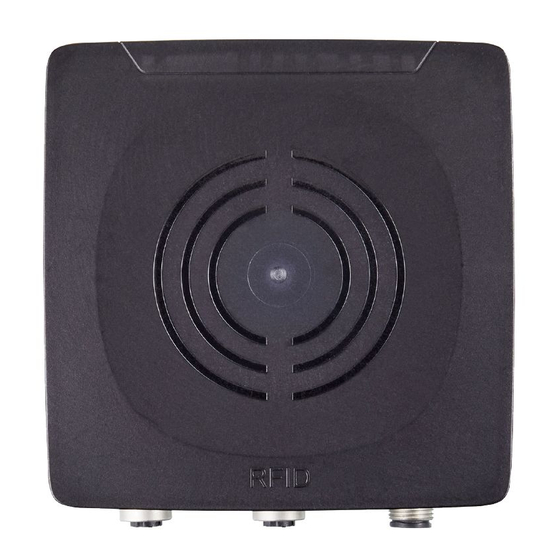
Type: rectangular Max� transmitter power: 2 watts Fig� 2: Overview DTE602 5.4 Overview DTE603 Art� no�: DTE603 Function: RFID compact unit Type designation: DTRHF HLRWECUS03 Operating frequency: 13�56 Mhz Type: rectangular Max� transmitter power: 2 watts Fig� 3: Overview DTE603... -
Page 8: 5�5 Overview Dte604
The immediate vicinity of powerful HF emission sources such as welding transformers or converters can affect operation of the RFID compact units� Available accessories: www�ifm�com 6.2 Notes on ID tag mounting Installation of the ID tags in and on metal reduces the read and write distances�... -
Page 9: 6�4 Mechanical Design
6.4 Mechanical design 1: sensing face 2: connection (can be rotated by 270°) Fig� 5: Mechanical design 6.5 Installation options For installation, the following optional accessories are available� The device can be mounted without the accessories� For installation, please use the threaded sleeves on the back of the device� The necessary screws are not supplied with the device�... -
Page 10: 6�5�2 Installation With Mounting Device E80336
6.5.2 Installation with mounting device E80336 The mounting device is used to fix the device to a clamp� The following clamps can be used: • E21110 with a rod diameter of 12 mm • E20795 with a rod diameter of 14 mm •... -
Page 11: 6�6 Mounting Distances
6.6 Mounting distances Fig� 9: Mounting distances Operating mode Distance side (A) Distance front (B) Read and write ≥ 850 mm ≥ 600 mm (at 100% transmitter power) 6.7 Positioning of the ID tags ► Align the ID tag on the antenna central axis�... -
Page 12: Electrical Connection
► Connect the device to the voltage supply using an M12 connection cable� Connection 24 V DC digital input / output 2 digital input / output 1 not connected Fig� 11: Pin connection voltage supply Matching connection cables are available: www�ifm�com... -
Page 13: 7�2 Ethernet
7.2 Ethernet ► Connect the device to a PC using a suitable M12 Ethernet connection cable� The M12 Ethernet cable must be screened to ensure interference-free operation� Connection Fig� 12: Pin connection fieldbus connection 7.2.1 Factory setting of the Ethernet parameters The following values are preset at the factory: Parameter Factory setting... -
Page 14: 7�3 Functional Earth Connection
7.3 Functional earth connection To ensure interference-free operation, the device must be connected to an earth potential free from external voltage� 7.3.1 Mounting plate When the device is fixed on a mounting plate, the connection is made via one of the four mounting bolts on the back�... -
Page 15: Operating And Display Elements
8 Operating and display elements ①: 1 power LED (green) 4 LEDs on signal bar (yellow) 2 fieldbus LEDs (green/red) ②: sensing face Fig� 14: Operating and display elements 8.1 Reset to factory settings The Ethernet parameters can be reset to factory setting� To do so, proceed as follows: ►... -
Page 16: 8�2 Led Indicators
8.2 LED indicators The following LED indicators apply to all DTE60x devices� 8.2.1 Power LEDs and signal bar LED PWR LED signal bar Status Note (1x green) (4x yellow) voltage supply OK 18 V ≤ U ≤ 36 V flashing at antenna (HF field) is 2 Hz deactivated... -
Page 17: 8�2�3 Special Device Led Indicators
8.2.3 Special device LED indicators Status Note PWR LED (green) on A firmware update is device is in the service mode necessary and can be LEDs of signal bar "emergency system started" executed via the web server� (yellow) flashing at 8 Hz PWR LED (green) on major error, device has to be hardware fault or permanent... -
Page 18: 8�3 Led Indicators Dte601
8.3 LED indicators DTE601 The following LED indicators only apply to DTE601� 8.3.1 LED SF LED red LED green Status Note no voltage supply check the voltage supply "node flash test", initiated by flashing PROFINET IO controller normal operation - overload flashing error at channel level - temperature... -
Page 19: 8�4 Led Indicators Dte602
8.4 LED indicators DTE602 The following LED indicators only apply to DTE602� 8.4.1 LED Mod (module status) LED red LED green Status Note no voltage supply check the voltage supply Device is not configured� There is no exchange of data: ►... -
Page 20: 8�4�2 Led Net (Network Status)
8.4.2 LED Net (network status) LED red LED green Status Note ► check the voltage supply ► If DHCP is activated, no IP address or no voltage check presence of a supply DHCP server in the network� The device has received an IP address�... -
Page 21: 8�5 Led Indicators Dte603
8.5 LED indicators DTE603 The following LED indicators only apply to DTE603� 8.5.1 RUN LED LED green Status Note INITIALISATION of the device check the voltage supply PRE OPERATIONAL device If this status is not reached, check flashing status settings of the device in the PLC�... -
Page 22: 8�6 Led Indicators Dte604
8.6 LED indicators DTE604 The following LED indicators only apply to DTE604� 8.6.1 LED SF LED red LED green Status Note no voltage supply check the voltage supply normal operation - overload flashing error at channel level - temperature - internal fault - undervoltage error at device level - temperature... -
Page 23: Technical Data
11.1.2 Europe Use in all EU countries� 11.2 EU declaration of conformity ifm electronic gmbh hereby declares that the DTE60x radio system corresponds to the directive 2014/53/EU� You can find the EU declaration of conformity on our website at www�ifm�com�... -
Page 24: Scale Drawing
12 Scale drawing 12,4 M12x1...
Need help?
Do you have a question about the DTE603 and is the answer not in the manual?
Questions and answers