IFM DTE801 Installation Instructions Manual
Rfid compact unit
Hide thumbs
Also See for DTE801:
- Operating instructions manual (27 pages) ,
- Operating instructions manual (25 pages)
Table of Contents
Advertisement
Quick Links
Advertisement
Table of Contents

Related Manuals for IFM DTE801


Summary of Contents for IFM DTE801
- Page 1 Installation instructions RFID compact unit DTE801 DTE802 DTE803 DTE804...
-
Page 2: Table Of Contents
3 Functions and features ����������������������������������������������������������������������������������������5 3�1 Configuration via Ethernet interface ��������������������������������������������������������������6 4 Items supplied������������������������������������������������������������������������������������������������������6 5 Function ���������������������������������������������������������������������������������������������������������������6 5�1 Operating principle ����������������������������������������������������������������������������������������6 5�2 Overview DTE801������������������������������������������������������������������������������������������7 5�3 Overview DTE802������������������������������������������������������������������������������������������7 5�4 Overview DTE803������������������������������������������������������������������������������������������7 5�5 Overview DTE804������������������������������������������������������������������������������������������8 6 Installation������������������������������������������������������������������������������������������������������������8 6�1 General installation instructions ���������������������������������������������������������������������8 6�2 Notes on ID tag mounting ������������������������������������������������������������������������������8... - Page 3 8�2�1 Power LEDs and signal bar ����������������������������������������������������������������17 8�2�2 LED signal bar ������������������������������������������������������������������������������������17 8�2�3 LED LINK/ACT ETH 1 / ETH 2 �����������������������������������������������������������18 8�2�4 Special device LED indicators ������������������������������������������������������������18 8�3 LED indicators DTE801 �������������������������������������������������������������������������������19 8�3�1 LED SF �����������������������������������������������������������������������������������������������19 8�3�2 LED BF �����������������������������������������������������������������������������������������������19 8�4 LED indicators DTE802 �������������������������������������������������������������������������������20 8�4�1 LED Mod (module status) �������������������������������������������������������������������20...
-
Page 4: Preliminary Note
► Measures to take� 1.3 Copyright and trademarks © All rights reserved by ifm electronic gmbh� No part of these instructions may be reproduced and used without the consent of ifm electronic gmbh� All product names, pictures, companies or other brands used on our pages are the property of the respective rights owners�... -
Page 5: Functions And Features
• read and write ID tags which conform to the system without contact, • DTE801: communication with the control level via PROFINET IO, • DTE802: communication with the control level via EtherNet/IP, • DTE803: communication with the control level via EtherCAT, •... -
Page 6: 3�1 Configuration Via Ethernet Interface
4 Items supplied • DTE80x RFID compact unit • Installation instructions The device is supplied without installation and connection accessories� In the event of incomplete or damaged items supplied, please contact ifm electronic� 5 Function 5.1 Operating principle The ID tags are operated passively, i�e� without battery� The energy required for operation is supplied by the RFID compact unit�... -
Page 7: 5�2 Overview Dte801
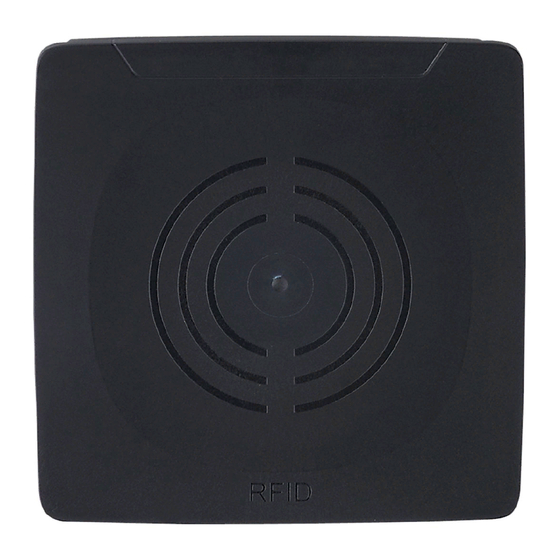
Type designation: DTRUHFE HLRWPNUS04 Operating frequency: 865 - 868 MHz Type: rectangular Typ� transmitter power: 23 dBm ERP (200 mW) Fig� 1: Overview DTE801 5.3 Overview DTE802 Art� no�: DTE802 Function: RFID compact unit Type designation: DTRUHFE HLRWEIUS04 Operating frequency:... -
Page 8: 5�5 Overview Dte804
The immediate vicinity of powerful HF emission sources such as welding transformers or converters can affect operation of the RFID compact units� Available accessories: www�ifm�com 6.2 Notes on ID tag mounting For installation in and on metal the ID tags provided for this purpose must... -
Page 9: 6�3 Avoiding Interference
The ID tag must be positioned in the area of the sensing face (→ „6.4 Mechanical design“)� The angle of aperture and the operating distance must be adhered to (→ Data sheet of the device). The orientation of the RFID compact unit axis must correspond with the axis of the ID tag�... -
Page 10: 6�5�1 Installation With Angle Bracket E80335
6.5.1 Installation with angle bracket E80335 Fig� 6: Installation with angle bracket E80335... -
Page 11: 6�5�2 Installation With Mounting Device E80336
6.5.2 Installation with mounting device E80336 The mounting device is used to mount the device to a clamp� The following clamps can be used: • E21110 with a rod diameter of 12 mm • E20795 with a rod diameter of 14 mm •... -
Page 12: 6�6 Mounting Distances
6.6 Mounting distances Fig� 9: Mounting distances Operating mode Distance side (A) Distance front (B) Reading and writing at 100% >6�0 m >10�0 m transmitter power (simultaneous operation) Reading and writing at 100% >0�3 m >0�3 m transmitter power (alternating operation) 6.7 Positioning of the ID tags ►... -
Page 13: Electrical Connection
► Connect the device to the voltage supply using an M12 connection cable� Connection 24 V DC digital input / output 2 digital input / output 1 not connected Fig� 11: Pin connection voltage supply Matching connection cables are available: www�ifm�com... -
Page 14: 7�2 Ethernet
7.2 Ethernet ► Connect the device to a PC using a suitable M12 Ethernet connection cable� The M12 Ethernet cable must be screened to ensure interference-free operation� Connection Fig� 12: Pin connection fieldbus connection 7.2.1 Factory setting of the Ethernet parameters The following values are preset at the factory: Parameter Factory setting... -
Page 15: 7�3 Functional Earth Connection
7.3 Functional earth connection To ensure interference-free operation, the device must be connected to an earth potential free from external voltage� 7.3.1 Mounting plate When the device is fixed on a mounting plate, the connection is made via one of the four mounting bolts on the back�... -
Page 16: Operating And Display Elements
8 Operating and display elements ①: 1 power LED (green) 4 LEDs on signal bar (yellow) 2 fieldbus LEDs (green/red) ②: Sensing face Fig� 14: Operating and display elements 8.1 Reset to factory settings The Ethernet parameters can be reset to factory setting� To do so, proceed as follows: ►... -
Page 17: 8�2 Led Indicators
8.2 LED indicators The following LED indicators apply to all DTE80x� 8.2.1 Power LEDs and signal bar LED PWR LED signal bar Status Note (1x green) (4x yellow) voltage supply OK 18 V ≤ U ≤ 36 V flashing at antenna (HF field) is 2 Hz deactivated... -
Page 18: 8�2�3 Led Link/Act Eth 1 / Eth 2
8.2.3 LED LINK/ACT ETH 1 / ETH 2 LED green LED yellow Status Note no connection to another link status "no link"“ Ethernet counterpart connection to Ethernet counterpart exists, no data link status "link", "no traffic" exchange connection to Ethernet flashes counterpart exists, data link status "link", "traffic"... -
Page 19: 8�3 Led Indicators Dte801
8.3 LED indicators DTE801 The following LED indicators only apply to DTE801� 8.3.1 LED SF LED red LED green Status Note no voltage supply check the voltage supply "node flash test", initiated by flashing PROFINET IO controller normal operation - temperature... -
Page 20: 8�4 Led Indicators Dte802
8.4 LED indicators DTE802 The following LED indicators only apply to DTE802� 8.4.1 LED Mod (module status) LED red LED green Status Note no voltage supply check the voltage supply Device is not configured� There is no exchange of data: ►... -
Page 21: 8�4�2 Led Net (Network Status)
8.4.2 LED Net (network status) LED red LED green Status Note ► check the voltage supply ► If DHCP is activated, no IP address or no voltage check presence of a supply DHCP server in the network� The device has received an IP address�... -
Page 22: 8�5 Led Indicators Dt803
8.5 LED indicators DT803 The following LED indicators only apply to DTE803� 8.5.1 RUN LED LED green Status Note INITIALISATION of the device Check the voltage supply� PRE OPERATIONAL device If this status is not reached, check flashing status settings of the device in the PLC� single SAFE OPERATIONAL state of If this status is not reached, check the... -
Page 23: 8�6 Led Indicators Dte804
8.6 LED indicators DTE804 The following LED indicators only apply to DTE804� 8.6.1 LED SF LED red LED green Status Note no voltage supply check the voltage supply normal operation - temperature flashing error at channel level - internal fault error at device level temperature flashing... -
Page 24: Technical Data
11.1.2 Europe Use in all EU countries� 11.2 EU declaration of conformity ifm electronic gmbh hereby declares that the DTE80x radio system corresponds to the directive 2014/53/EU� You can find the EU declaration of conformity on our website at www�ifm�com�... -
Page 25: Scale Drawing
12 Scale drawing 12,4 M12x1...
Need help?
Do you have a question about the DTE801 and is the answer not in the manual?
Questions and answers