IFM DTE601 Installation Instructions Manual
Rfid compact unit
Hide thumbs
Also See for DTE601:
- Operating instructions manual (21 pages) ,
- Installation instructions manual (25 pages)
Table of Contents
Advertisement
Advertisement
Table of Contents

Related Manuals for IFM DTE601


Summary of Contents for IFM DTE601
- Page 1 Installation instructions RFID compact unit DTE601 DTE602 DTE604 DTE605...
-
Page 2: Table Of Contents
3 Functions and features ����������������������������������������������������������������������������������������5 3�1 Configuration via Ethernet interface ��������������������������������������������������������������6 4 Items supplied������������������������������������������������������������������������������������������������������6 5 Function ���������������������������������������������������������������������������������������������������������������6 5�1 Operating principle ����������������������������������������������������������������������������������������6 5�2 Overview DTE601������������������������������������������������������������������������������������������7 5�3 Overview DTE602������������������������������������������������������������������������������������������7 5�4 Overview DTE604������������������������������������������������������������������������������������������7 5�5 Overview DTE605������������������������������������������������������������������������������������������8 6 Installation������������������������������������������������������������������������������������������������������������8 6�1 General installation instructions ���������������������������������������������������������������������8 6�2 Notes on ID tag mounting ������������������������������������������������������������������������������8... - Page 3 8�2�1 Power LEDs and signal bar ����������������������������������������������������������������16 8�2�2 LED LINK/ACT ETH 1 / ETH 2 �����������������������������������������������������������16 8�2�3 Special device LED indicators ������������������������������������������������������������17 8�3 LED indicators DTE601 �������������������������������������������������������������������������������18 8�3�1 LED SF �����������������������������������������������������������������������������������������������18 8�3�2 LED BF �����������������������������������������������������������������������������������������������18 8�4 LED indicators DTE602 �������������������������������������������������������������������������������19 8�4�1 LED Mod (module status) �������������������������������������������������������������������19...
-
Page 4: Preliminary Note
► Measures to take� 1.3 Copyright and trademarks © All rights reserved by ifm electronic gmbh� No part of these instructions may be reproduced and used without the consent of ifm electronic gmbh� All product names, pictures, companies or other brands used on our pages are the property of the respective rights owners�... -
Page 5: Functions And Features
the user and, if applicable, for any service personnel authorised by the manufacturer of the system� • Read this document before setting up the product and keep it during the entire service life� • The product must be suitable for the corresponding applications and environmental conditions without any restrictions�... -
Page 6: 3�1 Configuration Via Ethernet Interface
4 Items supplied • DTE60x RFID compact unit • Installation instructions The device is supplied without installation and connection accessories� In the event of incomplete or damaged items supplied, please contact ifm electronic� 5 Function 5.1 Operating principle The ID tags are operated passively, i�e� without battery� The energy required for operation is supplied by the RFID compact unit�... -
Page 7: 5�2 Overview Dte601
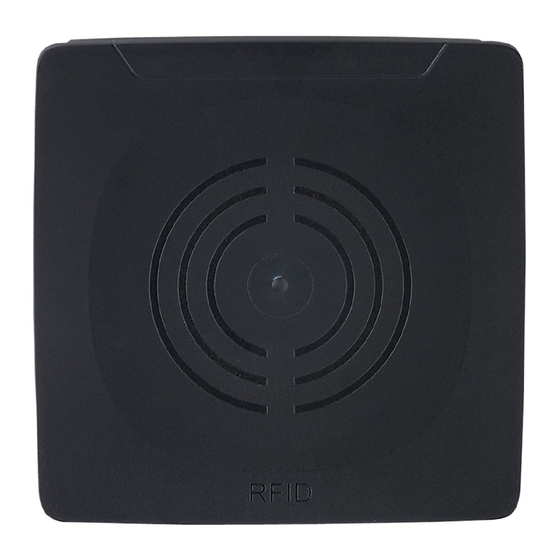
RFID compact unit Type designation: DTRHF HLRWPNUS03 Operating frequency: 13�56 Mhz Type: rectangular Max� transmitter power: 2 watts Fig� 1: Overview DTE601 5.3 Overview DTE602 Art� no�: DTE602 Function: RFID compact unit Type designation: DTRHF HLRWEIUS03 Operating frequency: 13�56 Mhz... -
Page 8: 5�5 Overview Dte605
The immediate vicinity of powerful HF emission sources such as welding transformers or converters can affect operation of the RFID compact units� Available accessories: www�ifm�com 6.2 Notes on ID tag mounting Installation of the ID tags in and on metal reduces the read and write distances�... -
Page 9: 6�4 Mechanical Design
6.4 Mechanical design 1: sensing face 2: connection (can be rotated by 270°) Fig� 5: Mechanical design 6.5 Installation options For installation, the following optional accessories are available� The device can be mounted without the accessories� For installation, please use the threaded sleeves on the back of the device� The necessary screws are not supplied with the device�... -
Page 10: 6�5�2 Installation With Mounting Device E80336
6.5.2 Installation with mounting device E80336 The mounting device is used to fix the device to a clamp� The following clamps can be used: • E21110 with a rod diameter of 12 mm • E20795 with a rod diameter of 14 mm •... -
Page 11: 6�6 Mounting Distances
6.6 Mounting distances Fig� 9: Mounting distances Operating mode Distance side (A) Distance front (B) Read and write ≥ 850 mm ≥ 600 mm (at 100% transmitter power) 6.7 Positioning of the ID tags ► Align the ID tag on the antenna central axis�... -
Page 12: Electrical Connection
► Connect the device to the voltage supply using an M12 connection cable� Connection 24 V DC digital input / output 2 digital input / output 1 not connected Fig� 11: Pin connection voltage supply Matching connection cables are available: www�ifm�com... -
Page 13: 7�2 Ethernet
7.2 Ethernet ► Connect the device to a PC using a suitable M12 Ethernet connection cable� The M12 Ethernet cable must be screened to ensure interference-free operation� Connection Fig� 12: Pin connection fieldbus connection 7.2.1 Factory setting of the Ethernet parameters The following values are preset at the factory: Parameter Factory setting... -
Page 14: 7�3 Functional Earth Connection
7.3 Functional earth connection To ensure interference-free operation, the device must be connected to an earth potential free from external voltage� 7.3.1 Mounting plate When the device is fixed on a mounting plate, the connection is made via one of the four mounting bolts on the back�... -
Page 15: Operating And Display Elements
8 Operating and display elements ①: 1 power LED (green) 4 LEDs on signal bar (yellow) 2 fieldbus LEDs (green/red) ②: sensing face Fig� 14: Operating and display elements 8.1 Reset to factory settings The Ethernet parameters can be reset to factory setting� To do so, proceed as follows: ►... -
Page 16: 8�2 Led Indicators
8.2 LED indicators The following LED indicators apply to all DTE60x devices� 8.2.1 Power LEDs and signal bar LED PWR LED signal bar Status Note (1x green) (4x yellow) voltage supply OK 18 V ≤ U ≤ 36 V flashing at antenna (HF field) is 2 Hz deactivated... -
Page 17: 8�2�3 Special Device Led Indicators
8.2.3 Special device LED indicators Status Note PWR LED (green) on A firmware update is device is in the service mode necessary and can be LEDs of signal bar "emergency system started" executed via the web server� (yellow) flashing at 8 Hz PWR LED (green) on major error, device has to be hardware fault or permanent... -
Page 18: 8�3 Led Indicators Dte601
8.3 LED indicators DTE601 The following LED indicators only apply to DTE601� 8.3.1 LED SF LED red LED green Status Note no voltage supply check the voltage supply "node flash test", initiated by flashing PROFINET IO controller normal operation - overload... -
Page 19: 8�4 Led Indicators Dte602
8.4 LED indicators DTE602 The following LED indicators only apply to DTE602� 8.4.1 LED Mod (module status) LED red LED green Status Note no voltage supply check the voltage supply Device is not configured� There is no exchange of data: ►... - Page 20 8.4.2 LED Net (network status) LED red LED green Status Note ► check the voltage supply ► If DHCP is activated, no IP address or no voltage check presence of a supply DHCP server in the network� The device has received an IP address�...
-
Page 21: 8�5 Led Indicators Dte604 / Dte605
8.5 LED indicators DTE604 / DTE605 The following LED indicators only apply to DTE604 / DTE605� 8.5.1 LED SF LED red LED green Status Note no voltage supply check the voltage supply normal operation - overload flashing error at channel level - temperature - internal fault - undervoltage... -
Page 22: Scale Drawing
12,4 M12x1 10 Technical data 10.1 Data sheet The data sheet is available on our website: www�ifm�com 10.2 Device manual The device manual is available on our website: www�ifm�com 11 Maintenance, repair and disposal If used correctly, no maintenance and repair measures are necessary�... -
Page 23: Approvals/Standards
The overview of the approval status of a unit is available on our website at www� ifm�com � 12.1.2 Europe / EC declaration of conformity ifm electronic gmbh hereby declares that the DTE60x radio system corresponds to the directive 2014/53/EU� You can find the EC declaration of conformity on our website at: www�ifm�com... -
Page 24: 12�1�4 Canada
12.1.4 Canada IC note: This device complies with Industry Canada license-exempt RSS standards� Operation is subject to the following two conditions: 1� The device may not cause interference, and 2� the user of the device must accept any interference received, including interference that may cause undesired operation�... -
Page 25: 12�1�6 Australia
12.1.6 Australia Use in Australia: 12.1.7 Singapore Complies with IDA Standards DB 103032 The “Equipment Registration” is available on our website at: www�ifm�com...
Need help?
Do you have a question about the DTE601 and is the answer not in the manual?
Questions and answers