Table of Contents
Advertisement
Quick Links
Advertisement
Table of Contents

Related Manuals for IFM DTE800


Summary of Contents for IFM DTE800
- Page 1 Operating instructions RFID UHF reader DTE800 DTE810 DTE900 DTE910 DTE920...
-
Page 2: Table Of Contents
RFID UHF reader Content 1 Preliminary note � � � � � � � � � � � � � � � � � � � � � � � � � � � � � � � � � � � � � � � � � � � � � � � � � 3 1�1 Symbols used�... -
Page 3: Preliminary Note
RFID UHF reader 1 Preliminary note This document is intended for specialists� These specialists are people who are qualified by their appropriate training and their experience to see risks and to avoid possible hazards that may be caused during operation or maintenance of the device�... -
Page 4: 2�3 Electrical Connection
LAN cable is connected� Connect a LAN cable to the device before you switch on the operating voltage� The connection pins may only be supplied with the signals indicated in the technical data and/or on the device label and only the approved accessories of ifm may be connected� 2.4 Tampering with the device In case of malfunctions or uncertainties please contact the manufacturer�... -
Page 5: 2�7�2 Fcc Labelling
2.7.2 FCC labelling The unit complies with the applicable requirements to FCC Part 15� Brand name: ifm electronic DTE900 and DTE910 RFID UHF reader for the US (FCC) This reader is designed for operation in accordance with FCC Part 15�... -
Page 6: 2�7�3 C-Tick Requirements
The “Equipment Registration” is available on our website at: www�ifm�com 3 Functions and features The multiprotocol-capable RFID reader DTE800 / DTE810 / DTE900 / DTE910 / DTE920 can be used to read active and passive RFID tags in different frequency ranges: ●... -
Page 7: Accessories
The following accessories are available for the reader� If you have any further questions, please do not hesitate to contact our sales department� 5.1 Antennas We recommend ifm electronic antennas, for example, ANT805, ANT810, ANT815, ANT820, ANT830, ANT910, ANT920 and ANT930� 5.2 Antenna cable Article 50-Ω... -
Page 8: Installation
RFID UHF reader 6 Installation 6.1 Installation location Provided that connections which are not used are covered, the unit complies with the protection rating IP65� When choosing the location of installation, provide for sufficient clear space to make sure that the heat generated inside the unit can properly dissipate�... -
Page 9: Connections And Displays
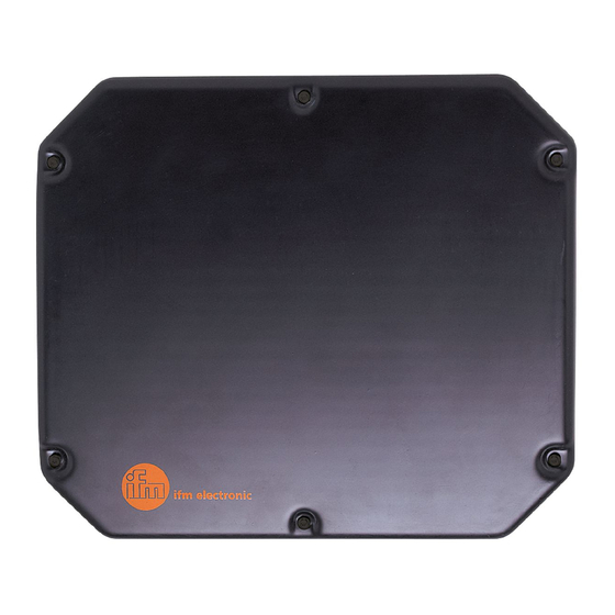
The following figure shows a reader with all connections� The connections as well as the pin connection of the plugs and sockets will be described in the following� Image: Overall view DTE800 / DTE810 / DTE900 / DTE910 / DTE920 ①... -
Page 10: 7�1 Voltage Supply
RD - Only use screened cables for Ethernet connection! 7.3 Inputs and outputs that are not electrically isolated The digital inputs and outputs of the DTE800/DTE900 are designed as two 5-pole sockets with A coding with M12 connection thread� Connection VCC (output for the supply of the digital outputs�... - Page 11 RFID UHF reader +U B INPUT 1 INPUT 1 INPUT 2 INPUT 2 Circuitry of the inputs not electrically isolated The digital outputs OUTPUT 1 and OUTPUT 2 are not electrically isolated from the operating voltage� +U B OUTPUT 1 OUTPUT 1 OUTPUT 2 OUTPUT 2...
-
Page 12: 7�4 Digital Inputs And Outputs
RFID UHF reader 7.4 Digital inputs and outputs The digital inputs and outputs of the DTE810/DTE910/DTE920 are designed as two 8-pole sockets with A coding with M8 connection thread� Assignment GPIO 1 Assignment GPIO 2 OUT_CMN (common switching output) OUT_CMN (common switching output) INPUT 4 (switching input 4) INPUT 1 (switching input 1) INP_CMN (common switching input) -
Page 13: 7�4�2 Digital Outputs
RFID UHF reader Circuitry of the inputs not electrically isolated 7.4.2 Digital outputs The outputs are also electrically isolated from the operating voltage of the reader and have a common pole (switching output CMN)� If the electrical isolation is not needed, the operating voltage can also be obtained directly from the reader�... -
Page 14: 7�5 Antenna Connection
RFID UHF reader Circuitry of the outputs not electrically isolated Load each digital input or output with max� 0�5 A� Load all digital inputs and outputs used with max� 1�5 A in total� If the auxiliary voltage of the GPIO connection of the reader is used, load all used digital inputs and outputs with all in all max�... -
Page 15: 7�6 Led
The configuration manual describes which parameters are available for the configuration of the reader� The reader is controlled via the ifm electronic proprietary reader protocol� The versions of the documents must correspond with the software version of the reader� The accompanying CD contains the up-to-date documents for the supplied reader firmware�...
Need help?
Do you have a question about the DTE800 and is the answer not in the manual?
Questions and answers