
Related Manuals for SCHUNK ROTA THW 400


Summary of Contents for SCHUNK ROTA THW 400
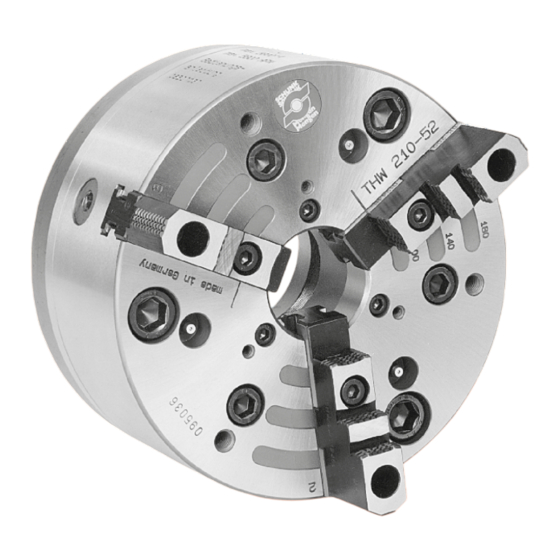
- Page 1 Power chuck ROTA THW / THWB Assembly and Operating Manual Translation of Original Operating Manual...
- Page 2 Imprint Imprint Copyright: This manual is protected by copyright. The author is SCHUNK SE & Co. KG. All rights reserved. Technical changes: We reserve the right to make alterations for the purpose of technical improvement. Document number: 0889110 Version: 04.00 | 19/07/2023 | en...
-
Page 3: Table Of Contents
Table of contents Table of Contents 1 General ..................... 5 About this manual................1.1.1 Presentation of Warning Labels ............. 1.1.2 Applicable documents ..............1.1.3 Sizes..................1.2 Warranty ................... 1.3 Scope of delivery................. 2 Basic safety notes ................2.1 Intended use..................2.2 Not intended use ................ - Page 4 Table of contents 4.2 Functional testing ................27 4.3 Handling the chuck and the base jaws............. 28 4.4 Base jaw position................29 4.5 Exchanging and turning the top jaws ............29 5 Transport ................... 30 6 Mounting ................... 31 6.1 Installing and connecting ..............31 6.2 Mounting the chuck onto the machine spindle ..........
-
Page 5: General
General 1 General 1.1 About this manual This manual contains important information for a safe and appropriate use of the product. This manual is an integral part of the product and must be kept accessible for the personnel at all times. Before starting work, the personnel must have read and understood this operating manual. -
Page 6: Applicable Documents
Catalog data sheet of the purchased product * Calculation of the jaw centrifugal forces, "Technology" chapter in the lathe chuck catalog * The documents labeled with an asterisk (*) can be downloaded from schunk.com. 1.1.3 Sizes This operating manual applies to the following sizes: ROTA THW 400;... -
Page 7: Basic Safety Notes
Structural changes should only be made with the written approval of SCHUNK. 04.00 | ROTA THW / THWB | Power chuck | en | 0889110... -
Page 8: Spare Parts
Use of unauthorized spare parts Using unauthorized spare parts can endanger personnel and damage the product or cause it to malfunction. Use only original spare parts or spares authorized by SCHUNK. 2.5 Chuck jaws Requirements of the chuck jaws Stored energy can make the product unsafe and poses the danger of serious injuries and considerable material damage. -
Page 9: Personnel Qualification
Basic safety notes 2.7 Personnel qualification Inadequate qualifications of the personnel If the personnel working with the product is not sufficiently qualified, the result may be serious injuries and significant property damage. All work may only be performed by qualified personnel. Before working with the product, the personnel must have read and understood the complete assembly and operating manual. -
Page 10: Notes On Safe Operation
Basic safety notes 2.9 Notes on safe operation Incorrect handling of the personnel Incorrect handling and assembly may impair the product's safety and cause serious injuries and considerable material damage. Avoid any manner of working that may interfere with the function and operational safety of the product. -
Page 11: Disposal
Basic safety notes 2.12 Disposal Handling of disposal The incorrect handling of disposal may impair the product's safety and cause serious injuries as well as considerable material and environmental harm. Follow local regulations on dispatching product components for recycling or proper disposal. 2.13 Fundamental dangers General Observe safety distances. -
Page 12: Protection During Commissioning And Operation
Basic safety notes 2.13.2 Protection during commissioning and operation Falling or violently ejected components Falling and violently ejected components can cause serious injuries and even death. Take appropriate protective measures to secure the danger zone. Never step into the danger zone during operation. 2.13.3 Protection against dangerous movements Unexpected movements Residual energy in the system may cause serious injuries while... -
Page 13: Notes On Particular Risks
Basic safety notes 2.13.4 Notes on particular risks DANGER Risk of fatal injury from suspended loads! Falling loads are sure to cause serious injuries and even death. Use suitable lifting equipment. Secure the product to prevent it from falling. Stand clear of suspended loads and do not step within their swiveling range. - Page 14 Basic safety notes DANGER Possible risk of fatal injury to operating personnel if a jaw breaks or if the lathe chuck fails because the technical data have been exceeded and a workpiece is released or parts fly off The technical data specified by the manufacturer for using the lathe chuck must never be exceeded.
- Page 15 Basic safety notes CAUTION Danger of limbs being crushed by opening and closing of the chuck jaws during manual loading and unloading or when replacing moving parts. Do not reach between the chuck jaws. Automatic loading is preferred. If manual loading is used, adjust the jaw position so that the opening gap between the jaw and the workpiece is less than 4 mm.
- Page 16 Basic safety notes CAUTION Hazard from vibration due to imbalanced rotating parts and noise generation. Physical and mental strains due to imbalanced workpieces and noise during the machining process on the clamped and rotating workpiece. Ensure the chuck's axial and concentric runout. Check options for remedying imbalances on special top jaws and workpieces.
-
Page 17: Technical Data
M [kgm] this data. Examples of calculation can be found in the "Technology" chapter of the SCHUNK lathe chuck catalog and Max. jaw eccentricity of center in the "Chuck jaws in special design/technology" chapter of of gravity in axial direction a the SCHUNK chuck jaws catalog. -
Page 18: Clamping Force / Speed Diagrams
The chuck is in perfect condition and lubricated with SCHUNK LINO MAX special grease. Should one or several of the above mentioned parameters be changed the diagrams are no longer valid. - Page 19 Technical data Clamping force / speed diagrams ROTA THW 500-128 required minimum clamping force 33% Speed n [min-1] Clamping force / speed diagrams ROTA THW 630-160 required minimum clamping force 33% Speed n [min-1] Clamping force / speed diagrams ROTA THWB 210-52 required minimum clamping force 33%...
- Page 20 Technical data Clamping force / speed diagrams ROTA THWB 265-71 required minimum clamping force 33% Speed n [min-1] Clamping force / speed diagrams ROTA THWB 315-86 required minimum clamping force 33% Speed n [min-1] Clamping force / speed diagrams ROTA THWB 400-120 required minimum clamping force 33%...
-
Page 21: Calculations For Clamping Force And Speed
Technical data Clamping force / speed diagrams ROTA THWB 500-128 required minimum clamping force 33% Speed n [min-1] Clamping force / speed diagrams ROTA THWB 630-160 required minimum clamping force 33% Speed n [min-1] 3.3 Calculations for clamping force and speed Missing information or specifications can be requested from the manufacturer. -
Page 22: Calculation Of The Required Clamping Force In Case Of A Given Rpm
Technical data 3.3.1 Calculation of the required clamping force in case of a given The initial clamping force F is the total force impacting radially on the workpiece via the jaws due to actuation of the lathe chuck during shutdown. Under the influence of rotation, the jaw mass generates an additional centrifugal force. - Page 23 Technical data The required effective clamping force for machining F calculated from the product of the machining force F and the safety factor S . This factor takes into account uncertainties in the calculation of the machining force. According to VDI 3106: S ≥...
-
Page 24: Calculation Example: Required Initial Clamping Force For A Given Speed
Technical data The centrifugal torque of the base jaws M can be found in the table "Lathe chuck data"} 3.1 [/ 17]. The centrifugal torque of the top jaws M is calculated as per: 3.3.2 Calculation example: required initial clamping force for a given speed Required initial clamping force F for a given RPM n... -
Page 25: Calculation Of The Permissible Speed In Case Of A Given Initial Clamping Force
Technical data Centrifugal torque for one jaw: The chuck has 3 jaws, the total centrifugal torque is: The total centrifugal force can now be calculated: Initial clamping force during shutdown that was sought: 3.3.3 Calculation of the permissible speed in case of a given initial clamping force Calculation of the permissible RPM n in case of a given initial... -
Page 26: Grades Of Accuracy
Technical data The calculated RPM n = 1495 RPM is smaller than the perm maximum permissible RPM of the lathe chuck n = 3200 RPM (see "Lathe chuck data" table } 3.1 [/ 17]). This calculated RPM may be used. 3.4 Grades of Accuracy Tolerances for radial and axial run-out accuracy correspond to the Technical Supply Terms for lathe chucks as per DIN ISO 3442-3. -
Page 27: Function
Function 4 Function 4.1 Function of the chuck The type THW quick-change power chucks are actuated using a rotating solid or open-center hydraulic cylinder. The axial tensile or pressure forces are converted to the radial jaw clamping force via wedge bars positioned tangentially to the chuck body. 4.2 Functional testing Functional test After installation of the chuck, its function must be checked prior... -
Page 28: Handling The Chuck And The Base Jaws
Function 4.3 Handling the chuck and the base jaws The clamping and opening path of the chuck jaws is determined by the clamping cylinder. The base jaws with screwed-on top jaws are moved or changed in the open clamping position. For safety reasons, the serration for the base jaws is still engaged in this chuck piston position. -
Page 29: Base Jaw Position
Function 4.4 Base jaw position A marking line between the jaw guides is milled on the face side of the chuck (see drawing} 9 [/ 39]). This marking line is the positioning aid for the base jaws or top jaws. The outermost base jaw or monoblock position is reached when the front face of the base jaw or the unsplit top jaw agrees with the marking line in the jaw change position (chuck open). -
Page 30: Transport
Transport 5 Transport DANGER Risk of fatal injury from suspended loads! Falling loads are sure to cause serious injuries and even death. Use suitable lifting equipment. Secure the product to prevent it from falling. Stand clear of suspended loads and do not step within their swiveling range. -
Page 31: Mounting
Mounting 6 Mounting 6.1 Installing and connecting WARNING Risk of injury due to unexpected movements! If the power supply is switched on or residual energy remains in the system, components can move unexpectedly and cause serious injuries. Before starting any work on the product: Switch off the power supply and secure against restarting. - Page 32 Mounting Piston in foremost position R1 = Push the chuck piston to its foremost position and measure with a depth gauge R2 = R1 + 0.3 mm (max. + 0.5 mm) You have to ensure that the piston can be moved to the foremost (jaw change) position.
- Page 33 Lubricating before commissioning the lathe chuck Before commissioning, move the chuck into the open position. Using a high-pressure grease press, press SCHUNK special grease LINOMAX into the lubricating nipple every 3 strokes. For optimal grease distribution and to achieve the maximum clamping force, close and open the chuck multiple times over the entire clamping stroke.
-
Page 34: Maintenance
Lubricate all three segments evenly in order to avoid imbalances. (For product information about LINOMAX, see the "Accessories" chapter of the SCHUNK lathe chuck catalog or contact SCHUNK.) CAUTION Allergic reactions if lubricating grease comes into contact with the skin. -
Page 35: Maintenance Intervals
Maintenance 7.2 Maintenance intervals Lubrication of the grease areas: Lubrication interval Strain every 25 hours normal / coolant utilization every 8 hours high / coolant utilization after 1200 hours or as Total cleaning with disassembly of the needed chuck, depending on type and degree of contamination 7.3 Technical condition With the smallest possible actuating pressure (hydraulic cylinder),... - Page 36 Lubricate thoroughly with LINOMAX grease before installation. Clean all individual components and check them for damage and wear. Only original SCHUNK spare parts may be used. The chuck is assembled in the same way, but in reverse order. Before installation, lubricate parts well with LINOMAX special grease paste.
-
Page 37: Chuck Mounts And Spare Parts
Z 220 800 031 ROTA THW 315-86 R 800 032 800 033 Z 220 800 040 Z 300 800 041 ROTA THW 400-120 R 800 042 A 11 800 043 Z 300 800 050 Z 380 800 051 A 11... -
Page 38: Spare Parts
Chuck mounts and Spare parts 8.2 Spare parts When ordering spare parts, it is imperative to specify the type, size and above all the manufacturing no of the chuck. Seals, sealing elements, screw connections, springs, bearings, screws and wiper bars plus parts coming into contact with the workpiece are not covered by the warranty. -
Page 39: Drawings
Drawings 9 Drawings 04.00 | ROTA THW / THWB | Power chuck | en | 0889110... - Page 40 Drawings 04.00 | ROTA THW / THWB | Power chuck | en | 0889110...
- Page 41 Drawings Marking line Base jaw 04.00 | ROTA THW / THWB | Power chuck | en | 0889110...
- Page 42 04.00 | ROTA THW / THWB | Power chuck | en | 0889110...
- Page 43 H.-D. SCHUNK GmbH & Co. Spanntechnik KG Lothringer Str. 23 D-88512 Mengen Tel. +49-7572-7614-0 Fax +49-7572-7614-1099 info@de.schunk.com schunk.com Folgen Sie uns I Follow us Wir drucken nachhaltig I We print sustainable...
- Page 44 2B, NCA, NCD, NCE, NC, NCF, NCK, NCO, NCR, NCS, NCX, TH, THW Heinz-Dieter SCHUNK GmbH & Co. Spanntechnik KG certifies that the above-mentioned products, when used as intended and in compliance with the operating manual and the warnings on the product, are safe according to the national regulations and: −...
Need help?
Do you have a question about the ROTA THW 400 and is the answer not in the manual?
Questions and answers