
Related Manuals for SCHUNK ROTA TB2 470-185


Summary of Contents for SCHUNK ROTA TB2 470-185
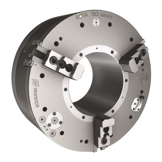
- Page 1 Translation of the original operating manual Pneumatic front-end chuck ROTA TB2 / ROTA TB2 LH Assembly and Operating Manual Superior Clamping and Gripping...
- Page 2 Imprint Copyright: This manual is protected by copyright. The author is SCHUNK GmbH & Co. KG. All rights reserved. Any reproduction, processing, distribution (making available to third parties), translation or other usage - even excerpts - of the manual is especially prohibited and requires our written approval.
-
Page 3: Table Of Contents
Table of contents Table of contents 1 General ........................5 1.1 About this manual ....................5 1.1.1 Presentation of Warning Labels ..............5 1.1.2 Applicable documents ................... 6 1.1.3 Sizes ....................... 6 1.2 Warranty ........................6 1.3 Scope of delivery ...................... 7 2 Basic safety notes .................... - Page 4 Table of contents 4 Torques per screw ....................35 5 Assembly ......................... 36 5.1 Pre-assembly measures ..................36 5.2 Distributor ring ....................... 37 5.2.1 Mounting with bracket ................38 5.2.2 Mounting with 2-part clamping ring (D.R.M.B.) ......... 40 5.3 Attachment of the ROTA TB2 chuck ............... 42 5.4 Optional mechanical pressure monitor with inductive proximity switch .....
-
Page 5: General
General General About this manual This manual contains important information for a safe and appropriate use of the product. This manual is an integral part of the product and must be kept accessible for the personnel at all times. Before starting work, the personnel must have read and understood this operating manual. -
Page 6: Applicable Documents
1.1.3 Sizes This operating manual applies to the following sizes: • ROTA TB2 470-185 / 470-185 LH • ROTA TB2 520-191 LH • ROTA TB2 600-275 / 600-275 LH • ROTA TB2 630-175 LH • ROTA TB2 685-325 / 685-325 LH •... -
Page 7: Scope Of Delivery
General Scope of delivery Lathe chuck ROTA TB2 (LH) T-nuts Elbow connectors Straight connectors 9 or 12 Fastening screws Eye bolt Operating manual 04.00|0889132_ROTA TB2 / ROTA TB2 LH |en... -
Page 8: Basic Safety Notes
Report any failures and damage immediately and repair without delay to keep the extent of the damage to a minimum and prevent compromising the safety of the product. Only original SCHUNK spare parts may be used. CONFIRMATION We hereby confirm that the components comply with the... -
Page 9: Not Intended Use
Spare parts Use of unauthorized spare parts Using unauthorized spare parts can endanger personnel and damage the product or cause it to malfunction. • Use only original spare parts or spares authorized by SCHUNK. 04.00|0889132_ROTA TB2 / ROTA TB2 LH |en... -
Page 10: Environmental And Operating Conditions
Basic safety notes Environmental and operating conditions Required ambient conditions and operating conditions Incorrect ambient and operating conditions can make the product unsafe, leading to the risk of serious injuries, considerable material damage and/or a significant reduction to the product's life span. •... - Page 11 Basic safety notes Functional test After installation of the lathe chuck, its function must be checked prior to commissioning. Two important points are: Clamping force! At max. actuating force/pressure, the clamping force specified for the lathe chuck must be reached. Stroke control! The pressure should be monitored by the lathe via mechanical pressure sensing via sensors or wirelessly via a RSS-P1.
- Page 12 Basic safety notes Option for path control of the control cam with stationary inductive proximity switch: Neither of the two proximity switches should be wired. When determining the clamping force required to machine a workpiece, the centrifugal force acting on the chuck jaws must be taken into account (according to VDI 3106).
- Page 13 Basic safety notes "Accessories" chapter of the SCHUNK lathe chuck catalog or contact SCHUNK.) • Use a suitable high-pressure grease gun to ensure that you reach all the greasing areas. • To ensure correct distribution of the grease, move the clamping piston to its end positions several times, lubricate again, and then check the clamping force.
- Page 14 • If the chuck is involved in a collision, it must be subjected to a crack test before using it again. Replace damaged parts with original SCHUNK spare parts. • Replace the chuck jaw mounting screws if there are signs of wear or damage.
-
Page 15: Substantial Modifications
Basic safety notes Caution Following a longer shutdown period (more than approx. 6 hours), always re-tension the clamped lathe chuck in order to compensate for the setting properties of the clamping situation or possible pressure losses and the resulting loss of clamping force. 2.6.1 Substantial modifications No substantial modifications may be made to the chuck. -
Page 16: Personal Protective Equipment
Basic safety notes Personal protective equipment Use of personal protective equipment Personal protective equipment serves to protect staff against danger which may interfere with their health or safety at work. • When working on and with the product, observe the occupational health and safety regulations and wear the required personal protective equipment. -
Page 17: Malfunctions
Basic safety notes 2.10 Malfunctions Behavior in case of malfunctions • Immediately remove the product from operation and report the malfunction to the responsible departments/persons. • Order appropriately trained personnel to rectify the malfunction. • Do not recommission the product until the malfunction has been rectified. -
Page 18: Protection During Handling And Assembly
Basic safety notes 2.12.1 Protection during handling and assembly Incorrect handling and assembly Incorrect handling and assembly may impair the product's safety and cause serious injuries and considerable material damage. • Have all work carried out by appropriately qualified personnel. •... -
Page 19: Notes On Particular Risks
Basic safety notes modifications, and attachments outside the danger zone defined by the movement range. • To avoid accidents and/or material damage, human access to the movement range of the machine must be restricted. Limit/prevent accidental access for people in this area due through technical safety measures. - Page 20 Basic safety notes DANGER Possible risk of fatal injury to operating personnel if a jaw breaks or if the lathe chuck fails because the technical data have been exceeded and a workpiece is released or parts fly off • The technical data specified by the manufacturer for using the lathe chuck must never be exceeded.
- Page 21 Basic safety notes CAUTION Danger of slipping and falling in case of dirty environment where the chuck is used (e.g. by cooling lubricants or oil). • Ensure that the working environment is clean before starting assembly and installation work. • Wear suitable safety shoes. •...
-
Page 22: 2-Jaw Chuck
Basic safety notes CAUTION Hazard from vibration due to imbalanced rotating parts and noise generation. Physical and mental strains due to imbalanced workpieces and noise during the machining process on the clamped and rotating workpiece. • Ensure the chuck's axial and concentric runout. •... -
Page 23: Technical Data
Torques per screw Technical data Chuck data ROTA TB2 470-185 600-275 685-325 850-375 1000-560 Outer diameter Ftk / 470 / 467 605 / 605 685 / 685 850 / 850 1000 / 925 distributor ring [mm] Distributor ring diameter [mm] Total clamping force at 6 bar [kN] Toolholder through-... - Page 24 Torques per screw ROTA TB2 470-185 520-191 600-275 630-275 850-375 1000-560 Overall stroke per 38.5 25.4 38.1 25.4 12.8 jaw [mm] Fast stroke / 13 / 7 30 / 8.5 16.9 / 8.5 28.1 / 10 13.4 / 12 15 / 10.4 clamping stroke [mm] Operating pressure...
-
Page 25: Clamping Force / Speed Diagrams
SHB, SWB and SWB-AL. The maximum actuating force was introduced and the jaws were placed flush with the base jaw outer edge. The chuck is in perfect condition and lubricated with SCHUNK LINO MAX special grease. Should one or several of the above mentioned parameters be changed the diagrams are no longer valid. - Page 26 Torques per screw Clamping force/RPM diagram for ROTA TB2 470-185 Clamping force/RPM diagram for ROTA TB2 600-275 Clamping force/RPM diagram for ROTA TB2 685-325 04.00|0889132_ROTA TB2 / ROTA TB2 LH |en...
- Page 27 Torques per screw Clamping force/RPM diagram for ROTA TB2 850-375 Clamping force/RPM diagram for ROTA TB2 1000-560 Clamping force/RPM diagram for ROTA TB2 470-185 LH 04.00|0889132_ROTA TB2 / ROTA TB2 LH |en...
- Page 28 Torques per screw Clamping force/RPM diagram for ROTA TB2 520-191 LH Clamping force/RPM diagram for ROTA TB2 600-275 LH Clamping force/RPM diagram for ROTA TB2 630-275 LH 04.00|0889132_ROTA TB2 / ROTA TB2 LH |en...
- Page 29 Torques per screw Clamping force/RPM diagram for ROTA TB2 850-375 LH Clamping force/RPM diagram for ROTA TB2 1000-560 LH 04.00|0889132_ROTA TB2 / ROTA TB2 LH |en...
-
Page 30: Calculations For Clamping Force And Speed
Torques per screw Calculations for clamping force and speed Missing information or specifications can be requested from the manufacturer. Legend Total centrifugal force [N] Centrifugal torque of top jaws [Kgm] Effective clamping force [N] Centrifugal torque of base jaws [Kgm] minimum required clamping force Speed of rotation [RPM] spmin... - Page 31 Torques per screw DANGER Risk to life and limb of the operating personnel and significant property damage when the RPM limit is exceeded! With gripping from the outside inwards, and with increasing RPM, the effective clamping force is reduced by the magnitude of the increasing centrifugal force (the forces are opposed).
-
Page 32: Calculation Example: Required Initial Clamping Force For A Given Speed
Torques per screw CAUTION This calculated force must not be larger than the maximum clamping force ΣS engraved on the lathe chuck. See also "Lathe chuck data" table ( 3.1, Page 23) From the above formula it is evident that the sum of the effective clamping force F and the total centrifugal force F is multiplied by... - Page 33 Torques per screw • Machining force F = 3000 N (application-specific) • max. RPM n = 3200 RPM ("Lathe chuck data" table) • RPM n = 1200 RPM (application-specific) • Mass of one (!) top jaw m = 5.33 kg (application- specific) •...
-
Page 34: Calculation Of The Permissible Speed In Case Of A Given Initial Clamping Force
Torques per screw 3.3.3 Calculation of the permissible speed in case of a given initial clamping force Calculation of the permissible RPM n in case of a given initial perm clamping force F The following formula can be used to calculate the permissible RPM for a given initial clamping force during shutdown: CAUTION For safety reasons, the calculated permissible RPM may not... -
Page 35: Grades Of Accuracy
Torques per screw Grades of Accuracy Tolerances for radial and axial run-out accuracy correspond to the Technical Supply Terms for lathe chucks as per DIN ISO 3442-3. Permissible imbalance The ROTA TB2 / ROTA TB2 LH in ungreased state without T-nuts and top jaws corresponds to the balancing quality class 6.3 (according to DIN ISO 21940-11). -
Page 36: Assembly
Assembly Assembly Pre-assembly measures Carefully lift the product (e.g. using suitable lifting gear) from the packaging. CAUTION Danger of injury due to sharp edges and rough or slippery surfaces Use personal protective gear, especially safety gloves. Check the delivery for completeness and for transport damage. Check the machine spindle head or machined intermediate flange for radial and axial runout. -
Page 37: Distributor Ring
Assembly Distributor ring The distributor ring is a completely separate component from the chuck and is centered and held stationary on the spindle head of the lathe axially and radially with a spacer bracket. After the first set-up of the chuck on the spindle nose of the lathe, the height of the spacer bracket is defined. -
Page 38: Mounting With Bracket
Assembly 5.2.1 Mounting with bracket The console height dimension is calculated by adding together the distances between the face side of the headstock and that of the distributor ring. If the headstock face surface is machined, the calculated dimension can be taken as the height dimension for the spacing console. - Page 39 Assembly True running check Dimensions of the console ROTA TB 470 (LH) TB 600 (LH) TB 630 LH TB 685 TB 850 (LH) TB 1000 (LH) Ø A Ø B* Ø C Ø D * Example only (deviations possible) 04.00|0889132_ROTA TB2 / ROTA TB2 LH |en...
-
Page 40: Mounting With 2-Part Clamping Ring (D.r.m.b.)
Assembly 5.2.2 Mounting with 2-part clamping ring (D.R.M.B.) It is possible to clamp the distributor ring to the machine by means of a 2-part clamping ring onto a rigid collar (at least 8 mm wide). In this case the distributor ring is clamped radially to this collar by means of two screws. - Page 41 Assembly Distributor ring mounting 04.00|0889132_ROTA TB2 / ROTA TB2 LH |en...
-
Page 42: Attachment Of The Rota Tb2 Chuck
A chuck flange is mounted on the spindle nose. 9 or 12 M16 or M24 hexagon socket screws are used to screw the chuck onto the chuck flange by the front face side. SCHUNK provides standard flanges that can be used to mount the ROTA TB2 chuck on spindles in accordance with DIN 55026, DIN 55027 and DIN 55029. -
Page 43: Optional Mechanical Pressure Monitor With Inductive Proximity Switch
Optional mechanical pressure monitor with inductive proximity switch If the chuck is ordered with the optional mechanical pressure monitoring (SCHUNK ID no. 0818205), this option is already integrated in the chuck. The monitoring function has been set to the working pressure of 6 bar. -
Page 44: Mechanical Stroke Monitoring With Inductive Proximity Switches On Dual Stroke Chucks
The right-hand inductive proximity switch should trigger when the dimension "L" of the control cam has the following dimension: ROTA TB2 470-185 LH: 29.4 mm ROTA TB2 520-191 LH: 28.7 mm ROTA TB2 600-275 LH: 28.1 mm ROTA TB2 630-275 LH: 24.1 mm... - Page 45 Assembly WARNING Risk of injury from ejected workpieces and risk of damage to the lathe chuck if the machine is started up despite the indication on the proximity switch display. • The machine may be released for machining only if the right inductive proximity switch responds and the left one does not! •...
-
Page 46: Function
Function Function The item numbers specified for the corresponding individual components relate to chapter drawings.( 13, Page 67) Principle of Operation The problem of air supply was solved by a stationary distributor ring with profiled ring seals arranged in it. Via passage openings in the two elastically radially flexible profile seals, the compressed air flows via a twin non-return valve to one of the two pressure chambers. -
Page 47: Air Transmission System
Function Air transmission system Air transmission The air is only transmitted when the lathe spindle is at a standstill via profile seals arranged radially in the distributor ring. The profile seal is designed in such a way that the outer upper surface part is larger than the surface of the passage openings. -
Page 48: Pilot Controlled Check Valve
Function CAUTION When actuating the clamping device (clamping or releasing), allow a short pause for ventilation between each shifting operation. This ventilation pause must be at least 0.5 seconds, depending on the length of the hose. We recommend using a 4/3 or 5/3 directional control valve for this (center position depressurized). -
Page 49: Faults, Causes And Solutions
Function Faults, causes and solutions Fault Causes and solutions O.D. or I.D. clamping: Valve system executes no switching movement: The chuck closes, but opens again Remove check valve system, clean bore and lightly right away oil, reinstall valve system. Audible escape of air under the Foreign object under the profile seals: distributor ring when control unit is Disassemble distributor ring, remove profile seals,... - Page 50 Function Fault Causes and solutions Dual stroke chuck: The overlap of the clamping stroke in the chuck When clamping the workpiece the 3 piston is insufficient. There is a danger that parts will indicator pins protrude from the be damaged in the force transmission area. front side more than 0.5 mm;...
-
Page 51: Commissioning And Maintenance
Commissioning and maintenance Commissioning and maintenance Commissioning The item numbers specified for the corresponding individual components relate to chapter drawings.( 13, Page 67) Check whether the jaw guides and the piston of the ROTA TB2 power chuck are sufficiently lubricated at the lubrication nipples countersunk into the base jaws;... -
Page 52: Maintenance
Turning, facing or finish-turning of the ROTA TB2 power chuck is not allowed. Drilling in the front face side of the chuck is permitted only after consulting the SCHUNK technical sales department. Maintenance A WEH-type maintenance unit, consisting of a filter, a water separator and an oiler, must be connected upstream of the power chuck. - Page 53 Commissioning and maintenance 1 Mounted directly from front: 2 bore 7 Required distance for removing the holes Ø L, depth C4 container 2 Lateral mounting with two retaining 8 Automatic condensate drain can be brackets (accessories) connected by means of a hose with Ø 6 inside 3 Protective metal cage with container 9 Pressure gauge, Ø...
- Page 54 Commissioning and maintenance Ø T G 1/8” G 1/8” Weight [kg] 0.760 (weight without pressure gauge) 110.5 Basic setting for oiler Chuck type Clamping Number of oil Oil quantity consumption/jaw strokes drops stroke at 6 bar ROTA TB2 470 (LH) — 5 –...
-
Page 55: Maintenance Intervals
Commissioning and maintenance first needs to be removed. The double check valve is removed from the bore hole and the bore hole and the valve are cleaned to remove dirt and any foreign bodies. The silencers (item 50) must be cleaned or renewed every 2 months or whenever they become blocked. -
Page 56: Hardened Reversible Jaws And Soft Top Jaws
Commissioning and maintenance Cleaning the silencer: Interval Demands every 2 months Clean the silencer, if necessary in case of severe contamination replace the silencer Please regularly check the lathe chuck for tightness by applying a clamping force tester over a longer period of time (> 10 min.). The clamping force should not drop during this period. -
Page 57: Disassembly And Assembly
Disassembly and assembly Disassembly and assembly The item numbers specified for the corresponding individual components relate to chapter drawings.( 13, Page 67) Disassembly and cleaning 1 Unscrew both the pneumatic quick coupling pieces from the distributor ring (item 8), and detach the distributor ring (item 8) from the spindle nose together with the bracket. - Page 58 Disassembly and assembly out of the chuck. Pull the bar and the bolts (items 89 and 91) out of the chuck; these parts are securely glued together. 6 Unscrew the locking screws with the O-rings (items 10 and 48) and remove the diaphragms (item 33) from the chuck. Remove the sound absorber (item 50).
-
Page 59: Assembly
The cylinder chamber of the chuck must be oiled. Jaw guidances in the chuck body, base jaws and piston at the wedge hooks are greased with SCHUNK LINO MAX special grease. Assembly 1 Tighten all screws to the torque specified in the chapter "Screw torques"... - Page 60 Disassembly and assembly 5 Allow the piston with the O-rings (item 40) to snap into the base jaw wedge hooks (item 2) and push it in up to the end of the stroke. 6 Insert the O-ring (item 43) and the sealing disk (item 5) with the O-ring (item 42) and tighten to the chuck body until firm and airtight using the hexagon socket screws (items 14, 21).
-
Page 61: Mounting Of Optional Mechanical Pressure Monitoring System
Disassembly and assembly 8.2.1 Mounting of optional mechanical pressure monitoring system In general, the working pressure may only be inspected for O.D. clamping. 1 Loosen set-screw (pos. 103) at the circumference of the chuck body. 2 Remove lock (pos. 69) with the extension (pos. 99) and the O- rings (pos. -
Page 62: Control Of Types Tb2, Tb2 Lh
TB2S, TB2S LH stationary power chucks Control of types TB2, TB2 LH An electropneumatic safety control block (24 V) is available to actuate the front-end power lathe chuck, consisting of a pressure control valve, pressure switch, 2 magnetic valves with automatic clamping time monitoring including 2 sensors, and 2 evaluation devices (see separate operating manual). -
Page 63: Power Chuck With Extended And Standard Jaw Stroke (Lh)
Power Chuck with extended and standard jaw stroke (LH) Power Chuck with extended and standard jaw stroke (LH) Do not use dual stroke chucks (LH series) for I.D. clamping. Also, do not clamp workpieces on the fast stroke, since this stroke executes very large jaw strokes but very low clamping forces (1). -
Page 64: Spare Parts
Spare parts Spare parts When ordering spare parts, it is imperative to specify the type, size and above all the manufacturing no of the chuck. Seals, sealing elements, screw connections, springs, bearings, screws and wiper bars plus parts coming into contact with the workpiece are not covered by the warranty. - Page 65 Spare parts ROTA TB2 470 (LH) O-ring DIN 3771 O-ring DIN 3771 O-ring DIN 3771 O-ring DIN 3771 O-ring DIN 3771 O-ring DIN 3771 O-ring DIN 3771 O-ring DIN 3771 O-ring DIN 3771 O-ring DIN 3771 Profile seal O-ring DIN 3771 Sound absorber Straight screw connection Swivel fitting...
- Page 66 Spare parts Assembly group mechanical pressure monitoring Item Designation Cams Piston Sleeve Bolt Thrust bolt Sleeve Set-screw Compression spring O-ring DIN 3771 O-ring DIN 3771 O-ring DIN 3771 Set-screw O-ring DIN 3771 Valve insert ROTA TB2 600-1000 (LH) Item Designation Insert Double check valve DIN 7984/8.8 cylindrical screw...
-
Page 67: Assembly Drawings
Assembly drawings Assembly drawings Scope of delivery for dual stroke ROTA TB2 470 (LH) only valve without chucks insert 04.00|0889132_ROTA TB2 / ROTA TB2 LH |en... - Page 68 Assembly drawings Mechanical pressure monitoring Valve insert 04.00|0889132_ROTA TB2 / ROTA TB2 LH |en...
-
Page 69: Translation Of The Original Declaration Of Incorporation
Product designation: Pneumatic power lathe chucks Type designation ROTA TB2 470-185 (LH) to ROTA TB2 1000-560 (LH) ID number 0818201,0818202, 0818212, 0818250, 0818222, 0818231,0818245, 0818204, 0818226, 0818216, 0818251, 0818225, 0818235, 0818246, 0818301,0818302, 0818312,...
Need help?
Do you have a question about the ROTA TB2 470-185 and is the answer not in the manual?
Questions and answers