VAT 650 Series Installation, Operating, & Maintenance Instructions
Pendulum control & isolation valve with logic interface
Hide thumbs
Also See for 650 Series:
Table of Contents
Advertisement
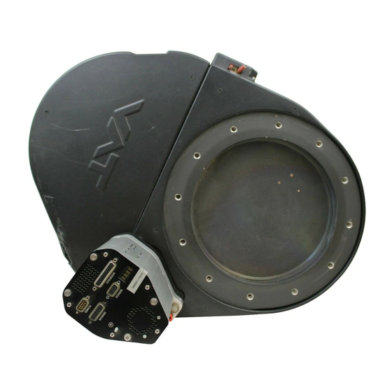
Pendulum control & isolation valve
with Logic interface
This manual is valid for the valve ordering number(s):
650 . . - . . GC - . . . .
650 . . - . . GE - . . . .
650 . . - . . AC - . . . .
650 . . - . . AE - . . . .
650 . . - . . HC - . . . .
650 . . - . . HE - . . . .
650 . . - . . CC - . . . .
650 . . - . . CE - . . . .
SPS = Sensor Power Supply
configured with firmware
The fabrication number is indicated on each product as per the label
below (or similar):
made in Switzerland
Fabrication No.:
patented
650 . . – . . . . – . . . . / . . . .
A – . . . . . .
Explanation of symbols:
Read declaration carefully before you start any other
action!
Attention!
Product is in conformity with EC guidelines!
Disconnect electrical power and compressed air
lines. Do not touch parts under voltage!
Read these «Installation, Operating & Maintenance Instructions» and the enclosed «General
Safety Instructions» carefully before you start any other action!
VAT Vakuumventile AG, CH-9469 Haag, Switzerland
Tel ++41 81 771 61 61 Fax ++41 81 771 48 30 Email
Installation, Operating & Maintenance Instructions
Series 650, DN 100 – 250 (I.D. 4" - 10")
(1 sensor input)
(2 sensor inputs)
(1 sensor input / ±15V SPS)
(2 sensor inputs / ±15V SPS)
(1 sensor input / PFO)
(2 sensor inputs / PFO)
(1 sensor input / ±15V SPS / PFO)
(2 sensor inputs / ±15V SPS / PFO)
PFO = Power Failure Option
650P.1D.00
. .
Fabrication number
reception@vat.ch www.vatvalve.com
Keep body parts and objects away from the valve
opening!
Hot surfaces; do not touch!
Loaded springs and/or air cushions are potential
hazards!
Wear gloves!
258550EE
2007-05-11
1/51
Advertisement
Table of Contents


Need help?
Do you have a question about the 650 Series and is the answer not in the manual?
Questions and answers